Tools Required
| • | J 24420-C Harmonic Balancer Puller |
| • | J 42845 Crankshaft Balancer Installer |
| • | J 42847 Flywheel Holding Tool |
Removal Procedure
- Remove the fan shroud. Refer to Fan Shroud Replacement in Engine Cooling.
- Remove the drive belt. Refer to Drive Belt Replacement .
- Raise and suitably support the vehicle with safety stands. Refer to Lifting and Jacking the Vehicle in General Information.
- Remove the starter motor. Refer to Starter Motor Replacement in Engine Electrical.
- Install the J 42847 to the starter bolt holes.
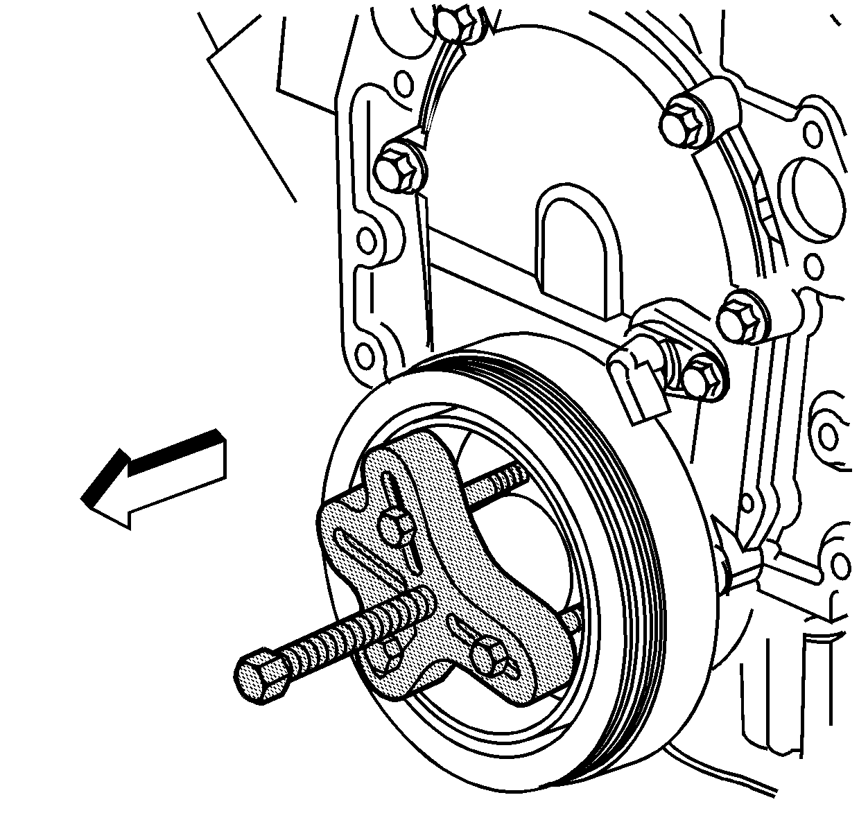
- Install the J 24420-C or equivalent onto the crankshaft balancer.
- Tighten the center screw of the J 24420-C until the crankshaft balancer is clear of the crankshaft nose.
- Remove the crankshaft balancer.
- Clean and inspect the crankshaft balancer. Refer to Crankshaft Balancer Cleaning and Inspection in the Engine Unit Repair Manual.

Notice: Use the correct fastener in the correct location. Replacement fasteners must be the correct part number for that application. Fasteners requiring replacement or fasteners requiring the use of thread locking compound or sealant are identified in the service procedure. Do not use paints, lubricants, or corrosion inhibitors on fasteners or fastener joint surfaces unless specified. These coatings affect fastener torque and joint clamping force and may damage the fastener. Use the correct tightening sequence and specifications when installing fasteners in order to avoid damage to parts and systems.
Important: Make sure the teeth of the flywheel holding tool engage the engine flywheel teeth.
Tighten
Tighten the J 42847
bolts to 50 N·m (37 lb ft).

Installation Procedure
Important:
• The balancer should be positioned onto the end of the crankshaft
as straight as possible prior to tool installation. • Apply grease or clean engine oil to the crankshaft balancer or
the end of the crankshaft to prevent galling during assembly.
- Install the balancer onto the end of the crankshaft.
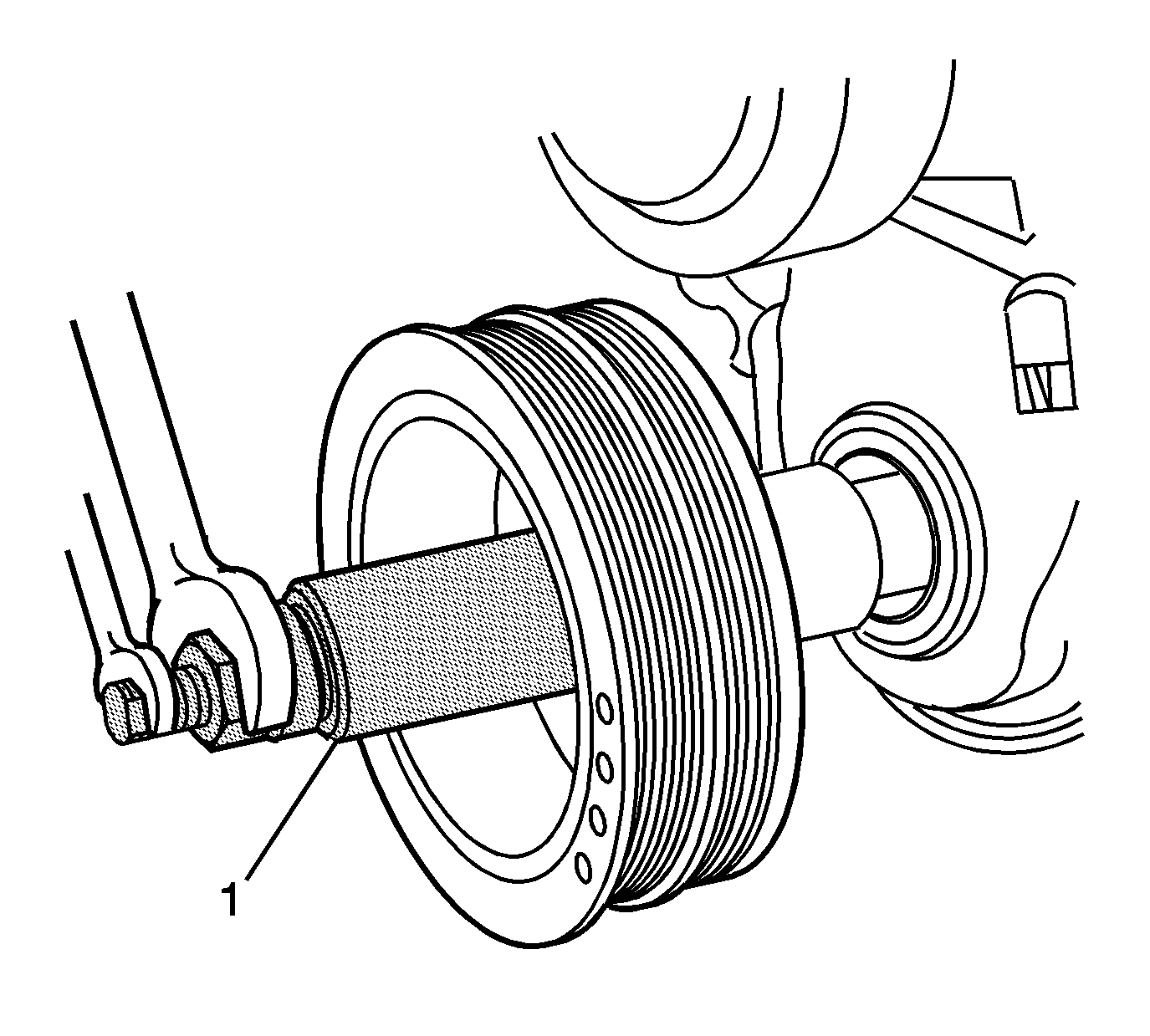
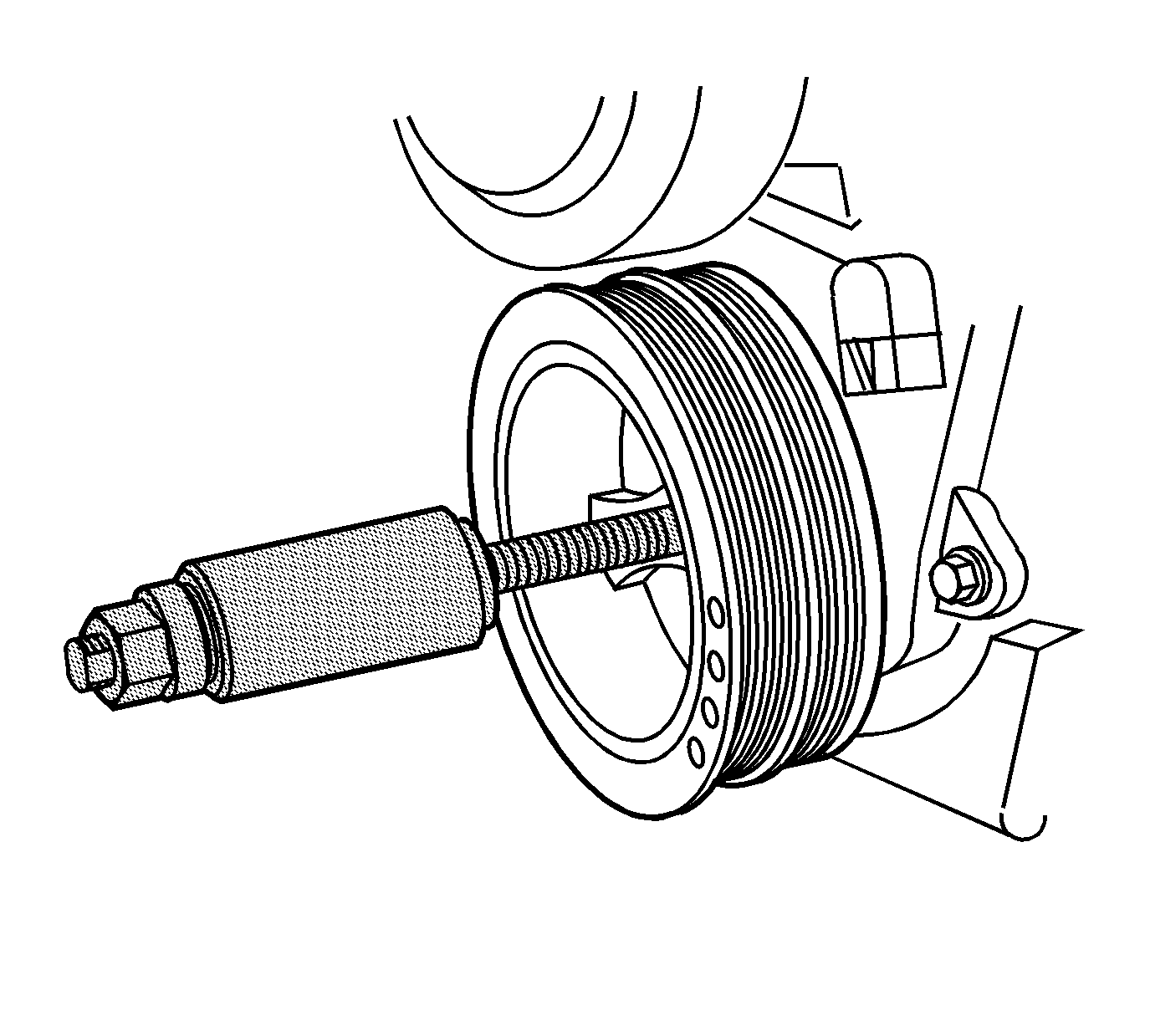
- Install the J 42845 to the crankshaft balancer.
- Using J 42845 install the balancer.
- Tighten the J 42845 until the crankshaft balancer is completely seated against the crankshaft sprocket.
- Remove the J 42845 from the crankshaft balancer.
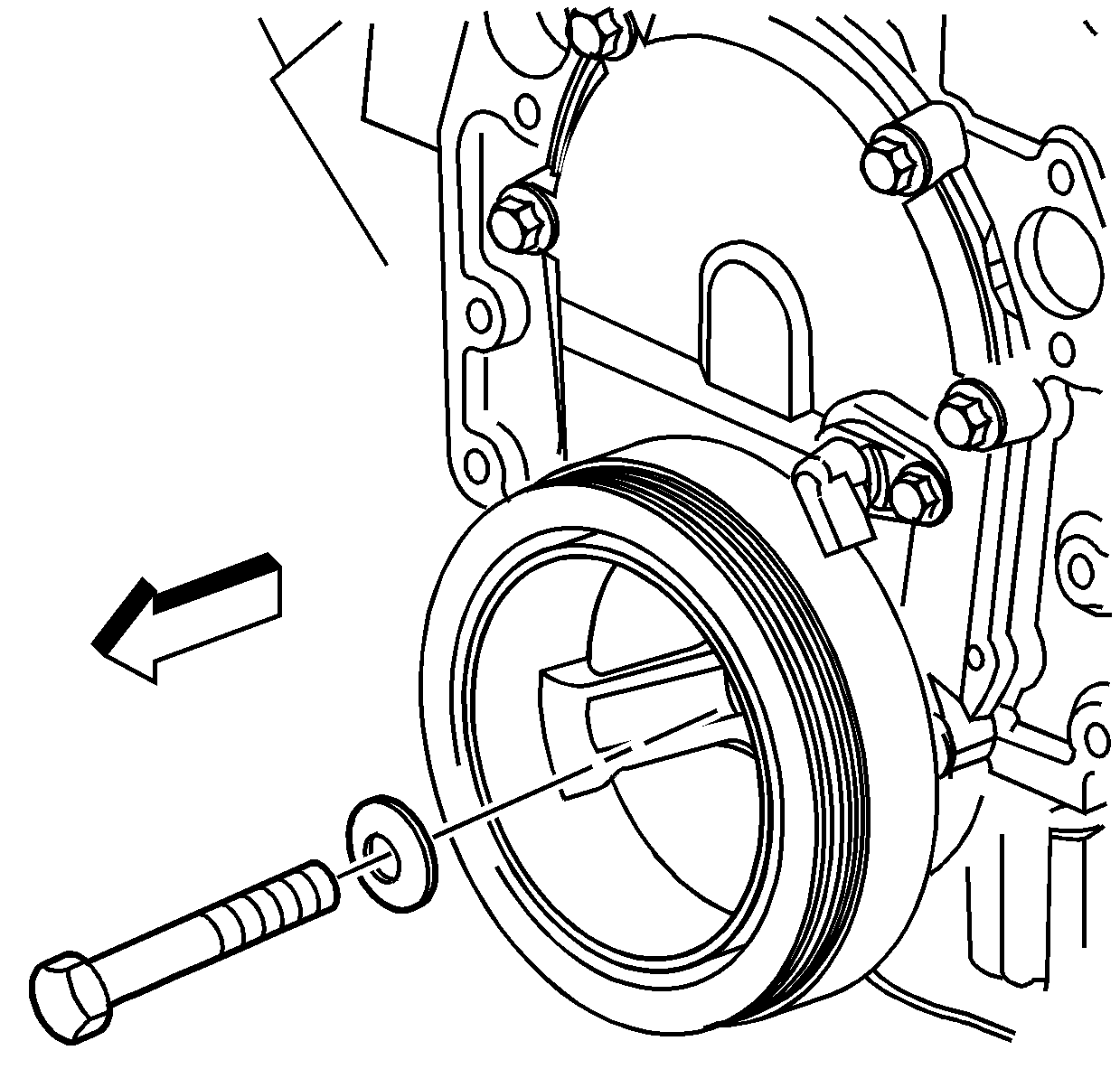
- Install the crankshaft balancer bolt and washer.
- Remove the J 42847 .
- Install the starter. Refer to Starter Motor Replacement in Engine Electrical.
- Install the drive belt. Refer to Drive Belt Replacement .
- Install the fan shroud. Refer to Fan Shroud Replacement in Engine Cooling.

Important: Apply the lubricant that comes with J 42845 each time the tool is used. Failure to lubricate J 42845 may prevent the balancer from installing completely.


Notice: Use the correct fastener in the correct location. Replacement fasteners must be the correct part number for that application. Fasteners requiring replacement or fasteners requiring the use of thread locking compound or sealant are identified in the service procedure. Do not use paints, lubricants, or corrosion inhibitors on fasteners or fastener joint surfaces unless specified. These coatings affect fastener torque and joint clamping force and may damage the fastener. Use the correct tightening sequence and specifications when installing fasteners in order to avoid damage to parts and systems.
Tighten
Tighten the crankshaft balancer bolt to 225 N·m (189 lb ft).
