This section covers the brake parts located at the wheels. For information on other air brake system components refer to Air Brake System Description and Operation in Air Brakes or Air Compressor Description and Operation in Air Compressor.
The air foundation brake assembly consists of the following components:
| • | The service brake chamber assembly |
| • | The spring brake chamber assembly |
| • | The slack adjuster |
| • | The camshaft brake assembly |
| • | The brake drum |
Brake Drum
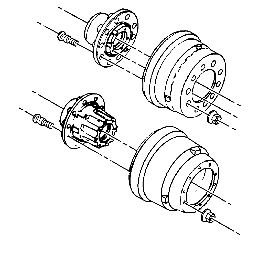
On all models the brake drum is fastened outboard of the hub by the wheel studs and nuts. You can remove an outboard-mounted brake drum after removing the tire and wheel assembly. You do not have to remove the hub and the wheel bearings.
Cam Brake Assembly
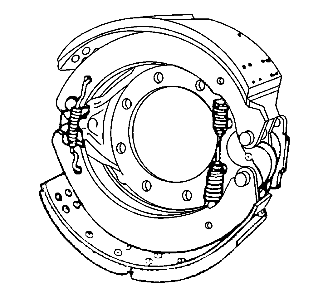
All air foundation brakes systems use cam type drum brakes. When the camshaft turns, the brake linings are forced outward in order to contract the brake drum. This provides the desired clamping action for braking.
Applying the brake pedal sends air pressure to the service brake chamber assembly at each wheel. The service brake chamber assembly pushrod moves the service brake automatic slack adjuster, rotating the camshaft, and expanding the brake shoes and the brake linings in order to contact the brake drum. Releasing the brake pedal allows air pressure to be exhausted from the service brake chamber assemblies. The pushrod return spring and the brake shoe return springs pull the brake shoes and the brake linings away from the brake drum.
The camshaft has an S-shaped cam on one end and splines on the other end. The camshaft splines fit together with the service brake automatic slack adjuster. The cam pushes against the brake shoe rollers in order to expand the brake shoes and the brake linings. The sealed bracket with bushings houses and supports the camshaft. The camshaft is lubricated through an external fitting in the bracket.
Slack Adjuster
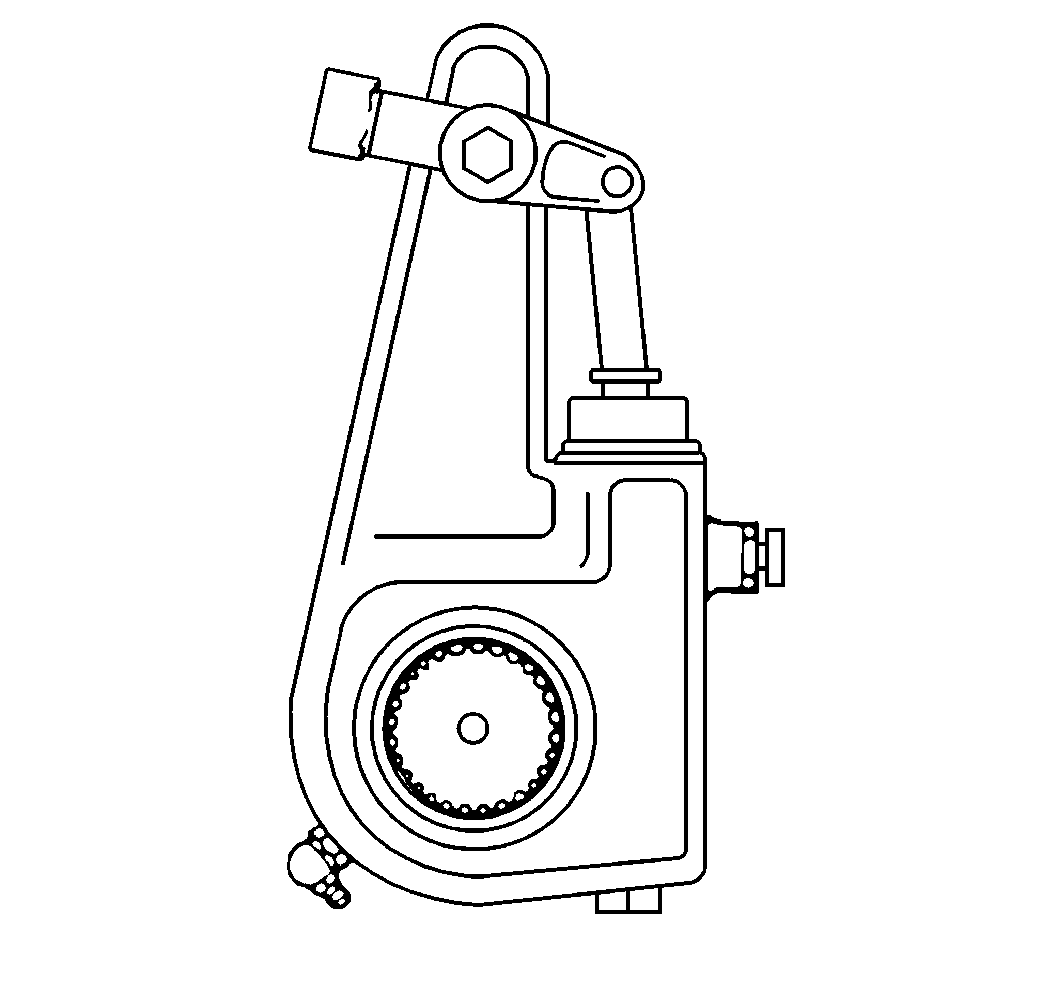
A slack adjuster mates with the camshaft splines and the slack adjuster acts as a lever to turn the camshaft. The slack adjuster contains a worm gear in order to adjust the angle in relation to the camshaft. This provides a way of adjusting the brakes to compensate for normal lining wear. Automatic adjusting slack adjusters are standard on all models.
The length of the service brake chamber stroke is set when the slack adjuster is installed. The length of the stroke is related to the clearance between the linings and the brake drum.
The clearance increases as the brake linings wear. The increased clearance makes the service brake chamber pushrod move a greater distance to apply the brakes.
The slack adjuster makes an adjustment during the return stroke of the pushrod if the stroke length exceeds the design limit. The adjustment corrects for lining wear and automatically resets the stroke to the correct length. The cycle then repeats.
Clevis
A clevis connects the end of the air brake chamber assembly pushrod to the slack adjuster. A clevis pin(s) fits through the clevis and slack adjuster end in order to allow the needed rotational movement.
Service Brake Chamber Assembly
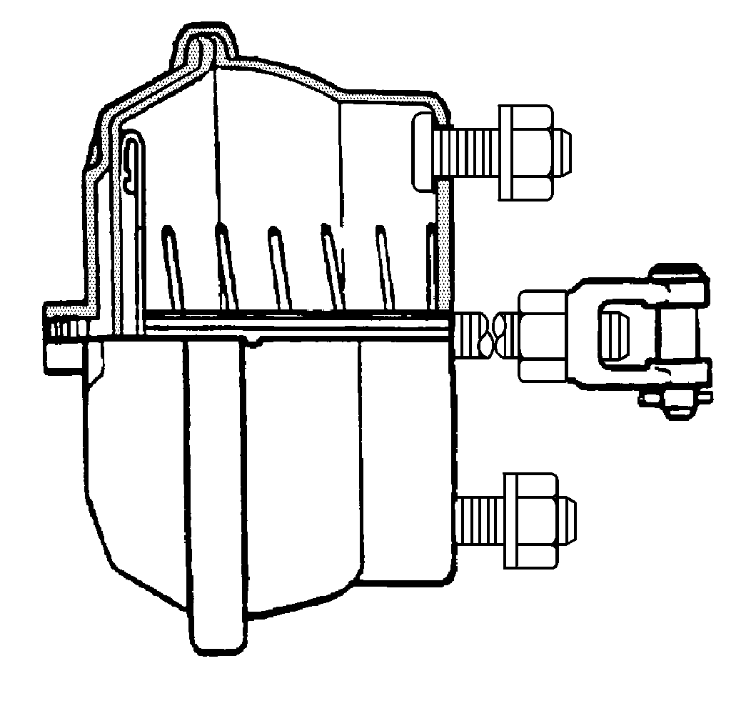
Service brake chamber assemblies use compressed air in order to create mechanical motion. Air pressure enters the sealed side of the service brake chamber assembly diaphragm and moves the pushrod outward. The moving diaphragm converts air pressure to mechanical movement. The diaphragm also seals the service brake chamber assembly in order to keep air from leaking out.
Spring Brake Chamber Assembly
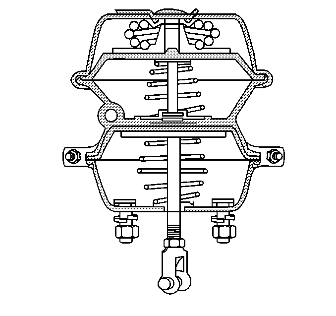
Only the rear axle uses spring brake chamber assemblies. Spring brake chamber assemblies have two separate air chambers mounted one behind the other. The front part is the service brake chamber assembly that is operated by the brake pedal. The spring brake chamber assembly has a large mechanical spring that forces the pushrod outward when air pressure is exhausted. Spring brake chamber assemblies provide fail-safe braking in emergencies or parking situations.
Sending air pressure to the spring brake chamber assemblies releases the parking brake. The air pressure compresses the diaphragm and the compression, power, spring in the spring brake chamber assemblies in order to release the brakes. When the brake pedal is applied, air enters the service brake chamber to apply the brakes. The compression, power, spring automatically begins to apply the brakes if air pressure drops below 655 kPa (95 psi). The brakes are fully applied when air pressure drops to 379 kPa (55 psi).
