Repairing Cracks
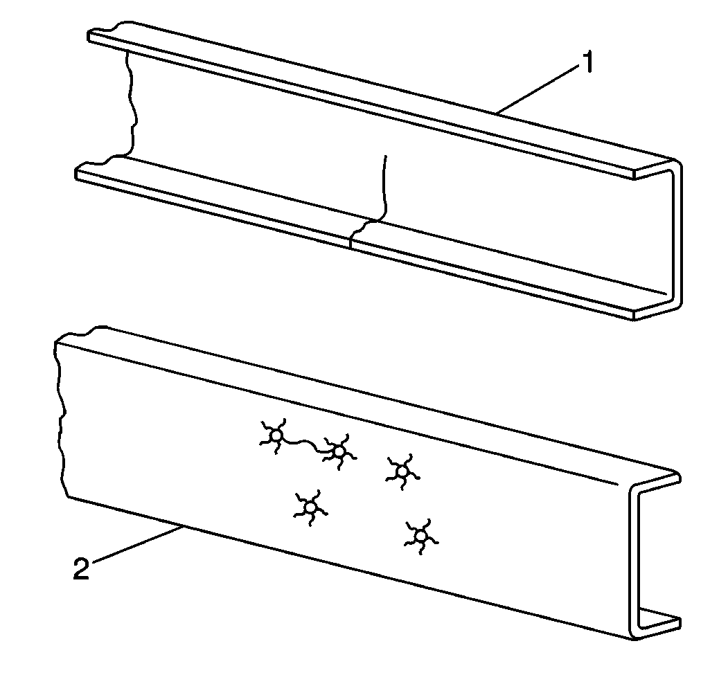
Straight cracks (1) and
sunburst cracks (2) are the two common types of cracks found in a frame.
A straight crack usually starts from the edge of a flange, spreads across
the flange, goes through the web section of the rail, and then continues
through the other flange. A straight crack results from stress concentrations,
excessive bending movement, and torsional loading. Refer to
Minimizing Frame Service Description
.
A sunburst crack radiates out from a hole in the web section of a rail
or a crossmember. Applying a high load at a mounting bracket or a crossmember
that is not securely attached to the rail may cause a sunburst crack.
If the rail and the reinforcement both crack at a particular area of
the frame, repair each part separately. The flanges must react independently
in order to prevent a localized stress concentration. Use a copper spacer
between the flanges of cracked base rail flanges and cracked reinforcement
flanges.
Use the same procedure for a crack in the crossmember mounting flange
as for a crack in the side rail. However, when repairing a crack in the crossmember
mounting flange, build up the weld bead in order to provide a smooth surface.
Replace any excessively damaged crossmembers.
You may need to align the frame and level the rails before repairing
the frame.
Use the following procedure in order to repair a crack in any rail,
reinforcement, or crossmember that is not made of a heat-treated steel:
- Remove any equipment inhibiting access to the crack.
- Drill a 6 mm (0.23 in) hole in the extreme end of
the crack.
- V grind the entire length of the crack from the starting point
to the 6 mm (0.23 in) hole in the extreme end. The angle of
the V depends on the type of welding process that is used. Refer to
Welding Table
for the appropriate
angle.
- Open up the bottom of the crack 2 mm (0.07 in) in
order to allow an adequate penetration of the weld using a hack saw blade.
- Weld the crack with the appropriate electrode and welding technique.
Refer to
Electrode Table
and
Welding Table
.
- Grind the weld until it is smooth on the inside and the outside
of the rail or the crossmember. Remove any weld build up or notches on the
edge of the flange.
Reinforcement Description
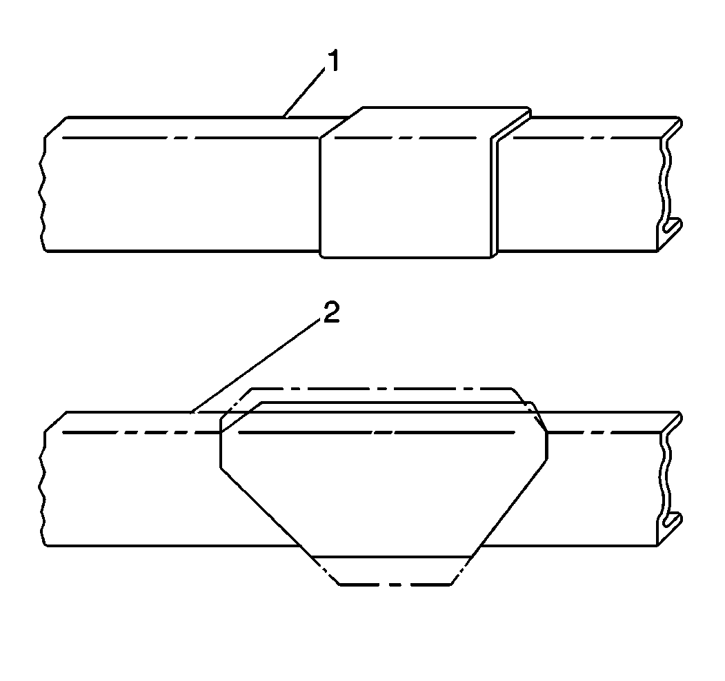
Reinforcements increase
frame strength by increasing the section modulus of the reinforced area. An
effective reinforcement must compensate for any factors that could cause
damage to the frame, while not introducing any new factors that may cause
stress concentrations. While a reinforcement is intended to make the frame
(1) less flexible, an excessively stiff reinforcement may cause frame
failure.
Adhere to the following guidelines when selecting the type or length
of a reinforcement:
| • | Use reinforced rails, rather than the heavier one-piece rails,
on a new vehicle. Add reinforcements if the unsupported span between the axles
is too great due to a long wheelbase. |
| • | Avoid abrupt changes in the section modulus by using tapered reinforcements. |
| • | Metals vary in type and strength. The strength of a reinforcement
should be as high as the frame that it being reinforced. Refer to
Yield Strength of Different Metals
. |
Reinforcement Types
| • |
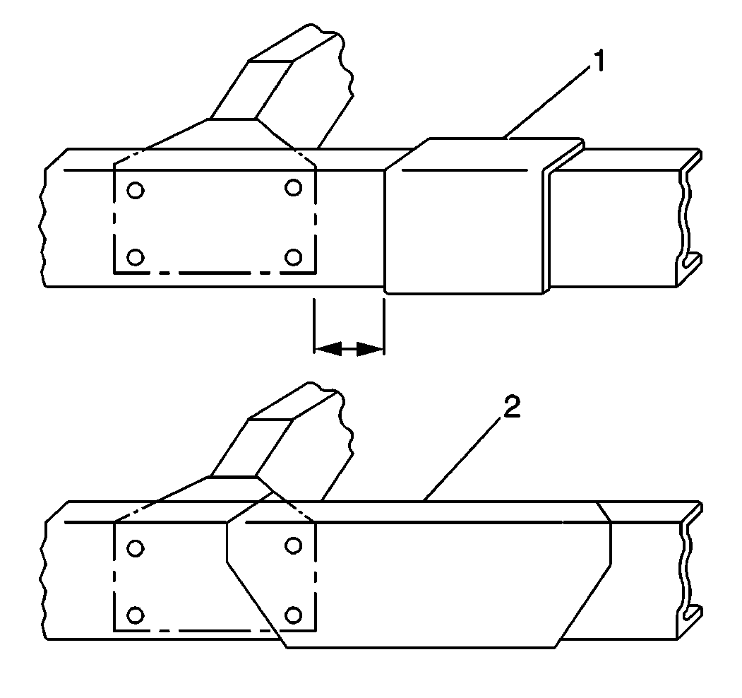
Any incorrect (1) reinforcement
practices may cause abrupt changes to the section modulus.Follow the correct (2) reinforcement practices carefully to avoid any
frame damage.
The following types of reinforcements may be combined in different ways
to meet any special needs (example: heavy demands).
|
| • |
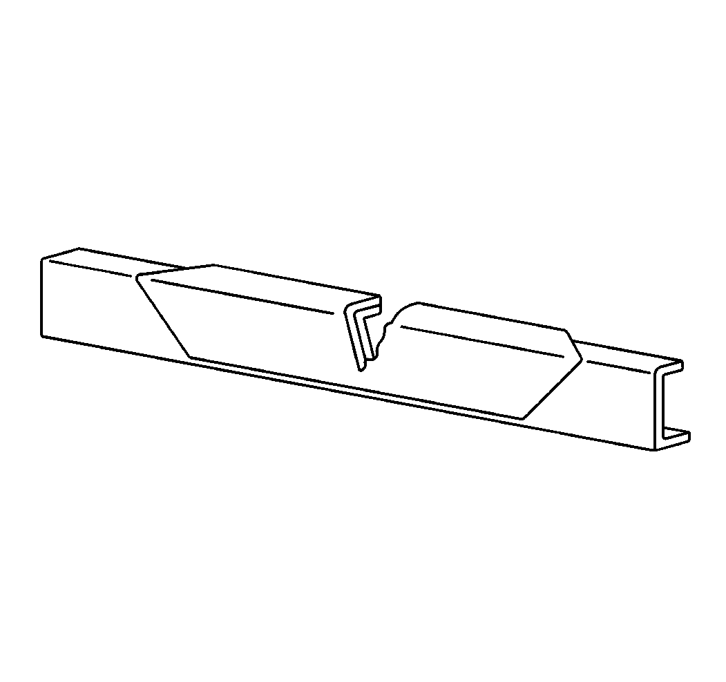
Use an inverted L reinforcement
on either the inside or the outside of the frame rail. Use the inverted L
reinforcement where the maximum stress occurs on the upper flange and
where the frame or hanger-bracket design does not allow the use of an
upright L reinforcement. |
| • |
Use channel reinforcements
on the inside or the outside of the frame rail in order to reinforce the flange
and the web rail. |
| • |
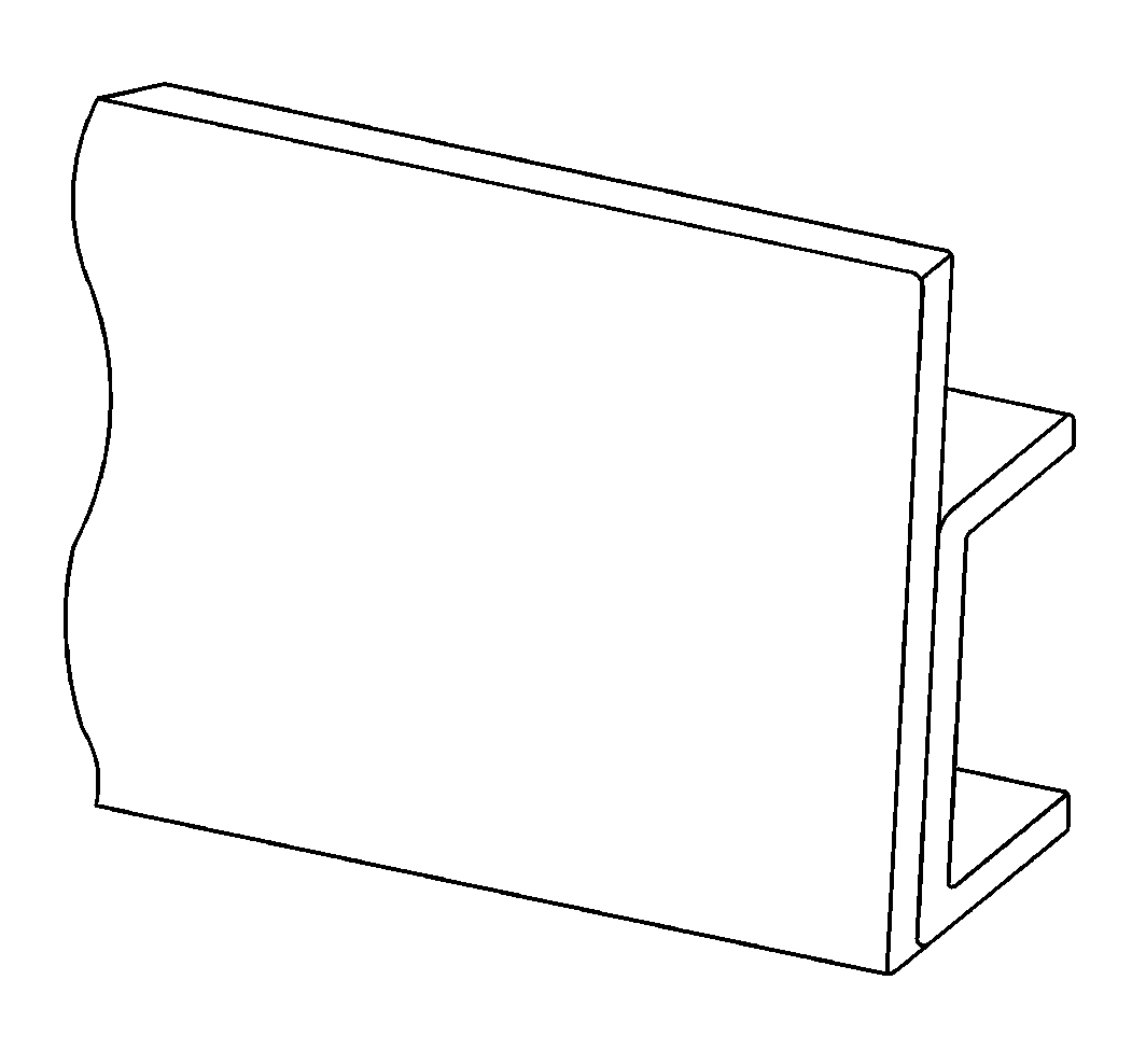
Use web reinforcements,
plug welded at 200-500 mm (7.87-19.68 in), on the
inside of the rail web. |
| • |
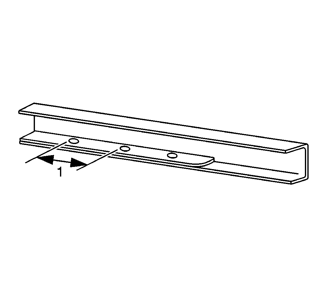
Use strap reinforcements,
plug welded at 150-200 mm (5.9-7.87 in) intervals
(1), on the rail flange on the inside of the channel. Do not weld across
the end or along the edges of the reinforcement. |
| • |
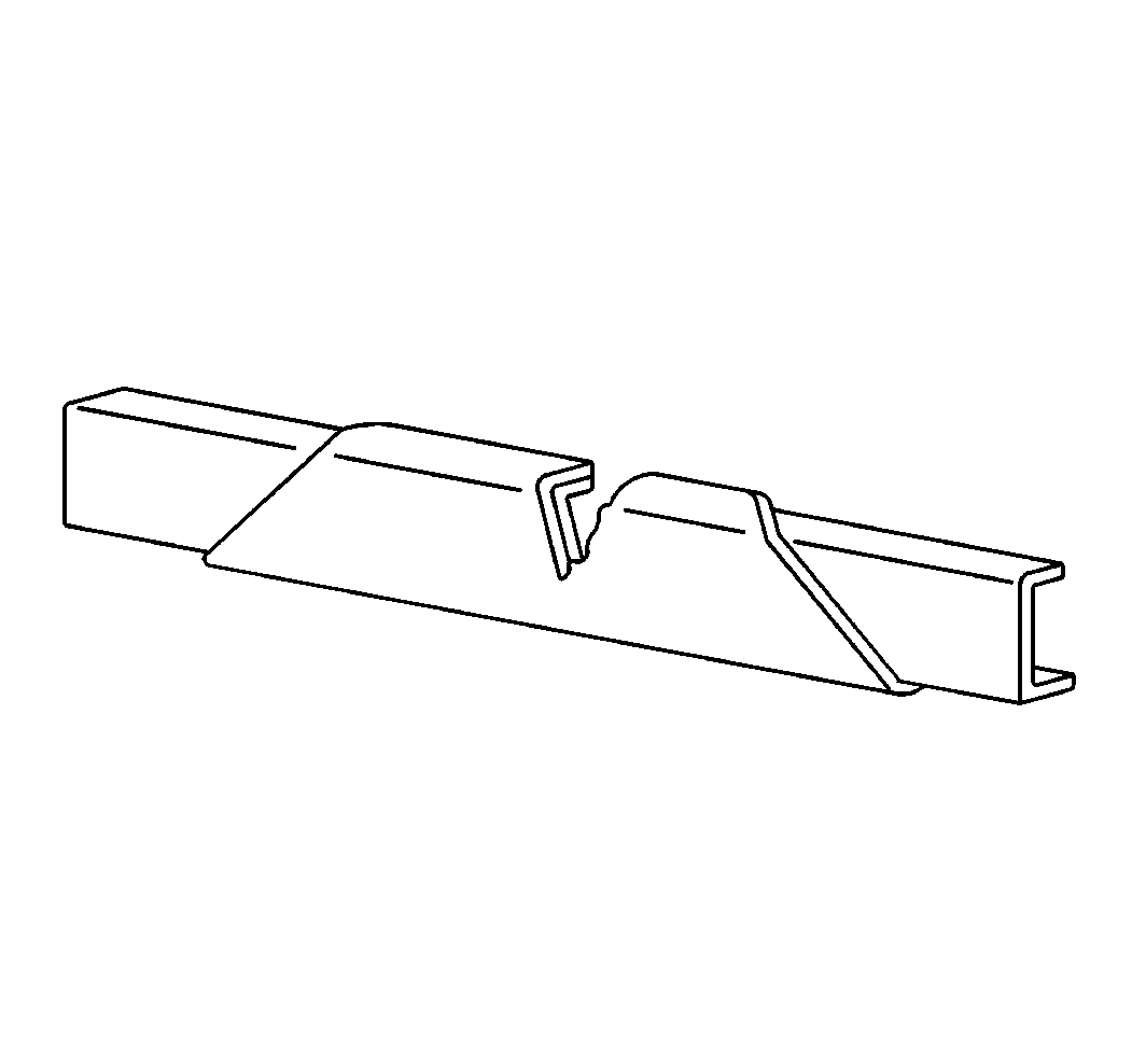
Use fish plate reinforcements
on the outside of the rail web, extending above or below the rail, to stiffen
the frame. |
| • |
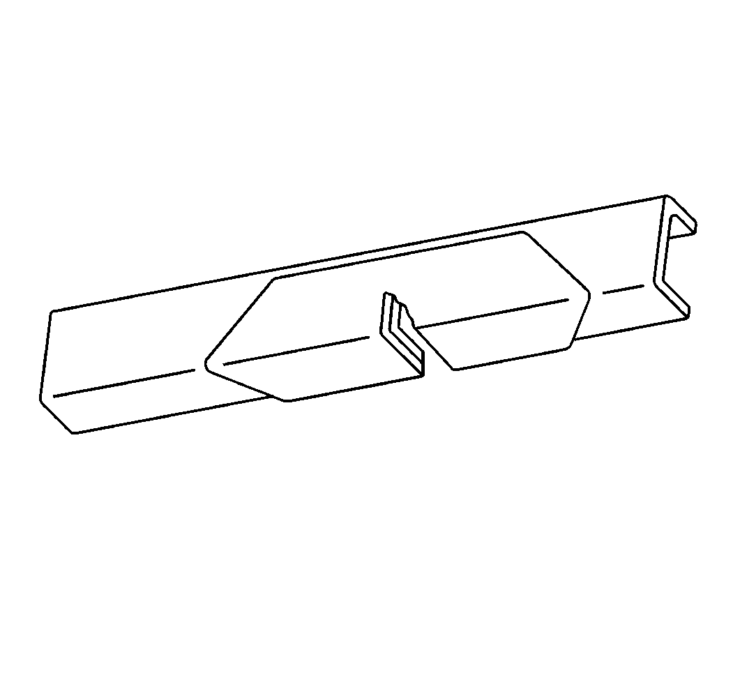
Use an upright L reinforcement
on the inside or the outside of the frame rail. Use an upright L reinforcement
where the maximum stress occurs on the bottom of the lower flange. |
| • |
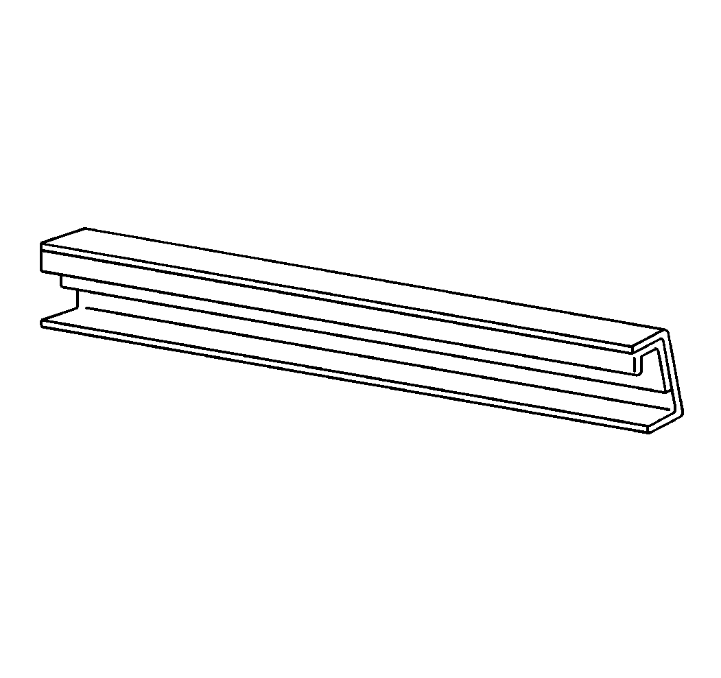
Use inverted J reinforcements,
attaching only to the web section, on the inside of the rail channel. The
inverted J reinforcement is designed to prevent any flange buckling due
to high torsional inputs or shock loading during a tractor hook-up operation. |
Creating Reinforcements
Observe the following practices when creating a reinforcement of any
type:
| • | Taper the reinforcement plates in order to avoid any abrupt changes
in the section modulus. Ensure that the angles at the edge of a reinforcement
plate are less than 45 degrees. |
| • | Grind away any cracks, nicks, or burrs when using a cutting torch
to shape the reinforcement plates. Remove any burrs from the edges of the
holes. |
| • | Avoid the gaps that may result when the reinforcements stop short
of the ends of the crossmembers, gussets and brackets. |
| • | Make the reinforcements long enough to extend beyond the critical
area, after tapering. |
Attachment
Attach all reinforcements with rivets or, preferably, bolts. In some
cases, welding may be acceptable. For example, a plug weld is used on a strap
or a web reinforcement. It is acceptable to ream an enlarged or irregularly
worn bolt hole in order for it to accept the next larger bolt diameter.
Body-fit bolts with hardened washers may be used on critical areas. When
using a body-fit bolt, ream the hole to a non-standard size to get an
interference fit for the bolt. Use existing holes whenever it is possible.
If it is necessary to make new holes, use a cobalt high-speed drill. Sharpen
the drill to give a 150 degree inclined angle with a lip clearance
of 7-15 degrees. Avoid enlarging a pilot hole in successive
stages and also avoid breaking through to the full size at the bottom
of the hole. Remove the lip of a hole with a reamer. Observe the following
guidelines when attaching reinforcement:
| • | Bolt the reinforcements to the frame. |
| • | Use existing holes if possible. |
| • | Do not drill holes in heat-treated frames. |
| • | Do not drill any holes in the frame flange. |
| • | Make the holes as close to the neutral axis (halfway between the
flanges) as possible. |
| • | Do not make any bolt holes larger than the holes already in the
frame, such as for the spring bracket bolts. |
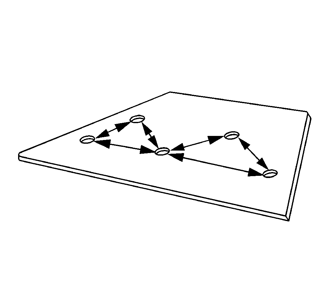
| • | Do not allow more than three holes on any particular vertical
line of the web. |
| • | All of the holes should be at least 13 mm (0.5 in)
apart from each other. |
| • | All of the holes in a reinforcement plate should be at least two
times the material thickness from the edge of the plate. |


