GM Service Manual Online
For 1990-2009 cars only

Key Identification and Usage

Engineers design the lock cylinder keyway in order that other model keys will not enter a lock cylinder from the current model year. GM vehicles have two non-interchangable keys:

    • A square headed key for the ignition
    • An oval headed key for all other lock cylinders

Identify keys by the four-character key code stamped onto the knockout portion of the key head and by the identification letter stamped onto the key shank. After the vehicle owner records the code number, knock the plugs out of the key head. Use the code numbers and a code list in order to determine the lock combination of the vehicle. The owners of key cutting equipment receive the code list from equipment suppliers. If the owner did not record the code number, determine the lock combination (tumbler level (2) and position (1)) by laying the key on the key code diagram.

Key Code Diagram
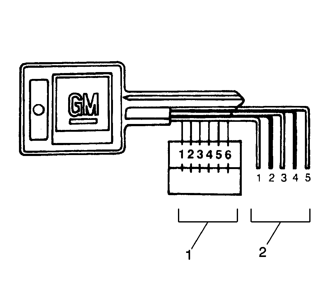

Object Number: 200598  Size: SH
(1)Position
(2)Levels

Cutting Keys

  1. Determine the code from the code list or the key code diagram.
  2. Cut a blank key to the proper level for each of the six tumbler positions.
  3. Ensure that the key locks and unlocks the lock cylinder.

Replacement Lock Cylinders

Lock cylinders are available from service parts warehouses. The new cylinder has a locking bar staked in place. Tumblers are also available from service parts warehouses. Insert the tumblers into the cylinder.

Assembling and Coding Lock Cylinders

All Lock Cylinders Except Instrument Panel Compartment


Object Number: 200599  Size: SH

Tumblers (4) for all locks have the same shape except for the notch position on one side. When the key inserts into the lock cylinder (2), the tumblers lower to the correct height. The tumblers lower so that the notches on each tumbler are at the same level. When the notches on all the tumblers line up, two small springs push the side bar (3) into the notches. The movement of the side bar allows the cylinder to turn in the cylinder bore. Five types of tumblers make various lock combinations. Each tumbler is coded according to a number (1-5) stamped on the side of the tumbler.

Assembly Procedure

  1. Perform the following steps in order to determine the numbers and arrangement of the tumblers
  2. 1.1. With the numerical key code, use the code list provided by a key cutting equipment supplier.
    1.2. Without the numerical key code or code list, use the following procedure:
             1.2.1. Lay the key on the key code diagram. Ensure that the diagram outlines the key.
             1.2.2. Start with position number one. Find and record the lowest visible tumbler number.
             1.2.3. Record the tumbler numbers of all five tumbler positions.

    Object Number: 200599  Size: SH
  3. Starting with position one - the open end or head of the cylinder, insert the tumblers (4) in the proper slots in the order that the code specifies.
  4. Pull the side bar (3) out in order to drop the tumblers completely into place.
  5. Insert one tumbler spring above each tumbler.

  6. Object Number: 200600  Size: SH
  7. Insert the spring retainer (2).
  8. Ensure that the end prongs slide into the slots at each end of the cylinder (3).
  9. Press the retainer down.
  10. Insert the key into the lock cylinder in order to verify proper installation.
  11. If the tumblers are properly installed, the side bar will drop down. If the side bar does not drop down, reassemble the lock cylinder.
  12. Notice: Use leather or wood at each vise jaw to prevent damage to the cylinder.

  13. Remove the key.
  14. Secure the lock cylinder in a vise with the spring retainer exposed.
  15. Stake the spring retainer securely in place at each end (1). Use a staking tool in order to stake the cylinder metal over the retainer.
  16. Lubricate all lock cylinders using GM multi-purpose lubricant GM P/N 12345120 (Canadian P/N 726548) or a light oil (5W30).

Instrument Panel Compartment Lock Cylinder


Object Number: 200602  Size: SH

The instrument panel compartment lock uses a lock cylinder (4) with snap-in tumblers (1). The lock cylinder has four or five tumbler positions. The number 1 or 2 position (closest to the cylinder head (2)) is a brass retainer tumbler. The 2-5 positions or 3-5 positions are standard tumbler positions depending on the cylinder type. Therefore you need only the last 4 or 5 tumbler combinations.

Determine the tumbler numbers and arrangement in order to assemble the lock cylinder. Refer to Key Identification and Usage, then install the tumblers.