Tire Runout Measurement
Correct the runout problem first, because the runout of a tire/wheel
assembly will directly affect the amount of imbalance and radial force variation.
As the amount of runout decreases, imbalance and force variation also decrease.
Important: Before measuring or attempting to correct excessive runout, carefully
inspect the tire for an uneven bead seat. The distance from the edge of the
ring to the concentric rim locating ring should be equal around the entire
circumference. If the beads are not seated properly, remount the tire.
Otherwise excessive runout and imbalance may result.
You can correct radial and lateral runout at the same time. Two methods
are available for measuring runout of the tire/wheel assemblies:
Make an initial on-car visual inspection prior to performing the off-car
runout tests.
Measuring the tire/wheel runout off of the vehicle is the easier method
for the following reasons:
| • | You can mount a dial indicator in the correct location easier. |
| • | Chances of water, snow, dirt, or slush getting on the dial indicator
are decreased. |
| | Important: A dial indicator is a very fragile and expensive tool that you will
use extensively in vibration repair work. Contamination from outside elements
or from rough handling will usually result in breakage.
|
Once you have measured and corrected the runout off the vehicle, a quick
examination of runout on the vehicle will indicate if any further problems
exist. Refer to
Tire and Wheel Assembly Runout Measurement - On-Vehicle
.
If the off-vehicle measurement differs significantly from the on-vehicle
measurement, the runout problem is due to one of the following:
Measuring Tire Runout
Tools Required
| • | J 7872 Magnetic
Base Dial Indicator Set |
| • | J 23672 Dial
Indicator Roller Adapter |
If the vehicle has been sitting in one place for a long time, flat spots
may exist at the point where the tires were resting on the ground. These flat
spots will affect the runout readings. Before you take any runout measurements,
eliminate these flat spots by driving the vehicle long enough to warm
up the tires.
- Lift the vehicle on a hoist or support the vehicle with jackstands.
Refer to
Lifting and Jacking the Vehicle
in General Information.
- In order to get an initial indication of how much runout exists,
spin each tire and wheel on the vehicle by hand. You may also use the engine
at a slow speed in order to drive the wheels. Visually inspect the amount
of runout from the front or the rear.
- Mark the location of each tire/wheel assembly in relation to the
wheel studs and to their position on the vehicle for future reference.
- Remove the tire/wheel assemblies one at a time. Mount each assembly
on a spin-type wheel balancer. Locate the tire/wheel assembly on the balancer
with a cone through the back side of the center pilot hole.

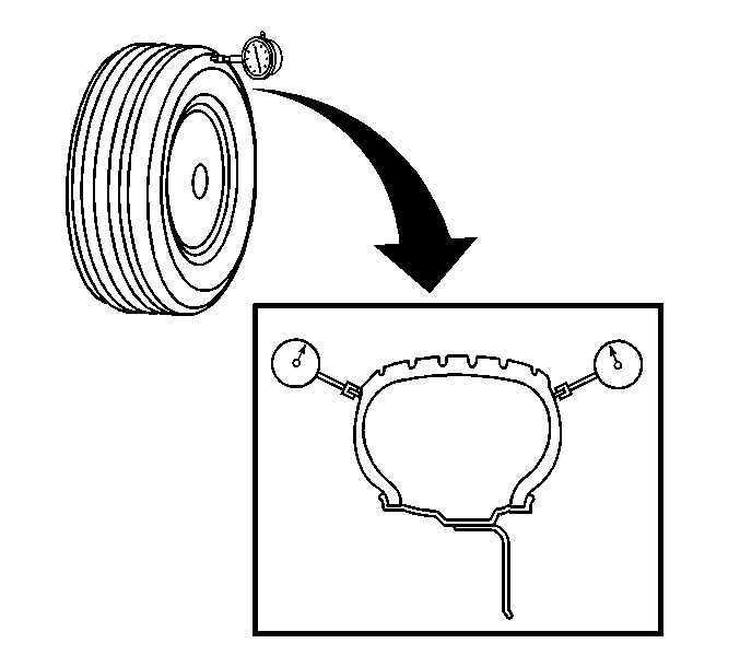
- For lateral runout place
the dial indicator in a smooth area on the tire sidewall as close to the tread
as possible.
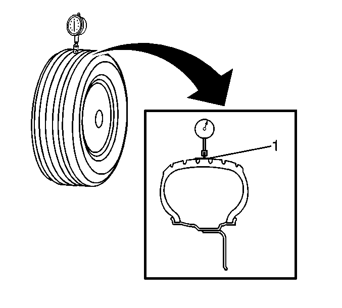
Measure the tire/wheel assembly runout as shown in the figure.

For radial runout, wrap the outer circumference with tape when you measure
the radial runout. This allows for a smooth reading from the dial indicator.
Ignore any jumps or dips due to sidewall splices.
Use either of the following dial indicator sets with roller contact
point J 23672
when applying
this procedure:
- Load the indicator and slowly rotate the assembly one complete
revolution.
- Set the indicator to zero on the low spot.
- Rotate the assembly one more complete revolution and note the
total amount of runout indicated. The maximum allowable assembly radial and
lateral runout is 3.1 mm (0.125 in).


