GM Service Manual Online
For 1990-2009 cars only
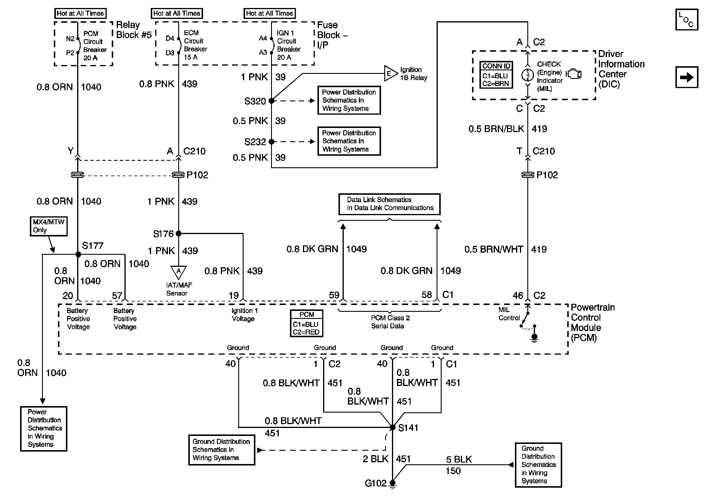
Figure 1:

Data Link Connector (DLC), Powertrain Control Module (PCM), Power and Ground

Object Number: 788241  Size: FS
Master Electrical Component List
Engine Controls Schematics - Power Distribution for Ignition Coils and Fuel Injectors
Power Distribution Schematics - IGN 1 Circuit Breaker, S225, S226, S230
Power Distribution Schematics - IGN 1 Circuit Breaker, S232, S243
Data LInk Connector (DCL) Schematics - L18
Engine Controls Schematics - Intake Air Temperature (IAT)/Mass Air Flow (MAF) and Manifold Absolute Pressure (MAP) Sensors
Power Distribution Schematics - ODD INJ and PCM Circuit Breakers L18
02Ground Distribution Schematics - S141 and S210 L18
Ground Distribution Schematics - G102, and S138 L18
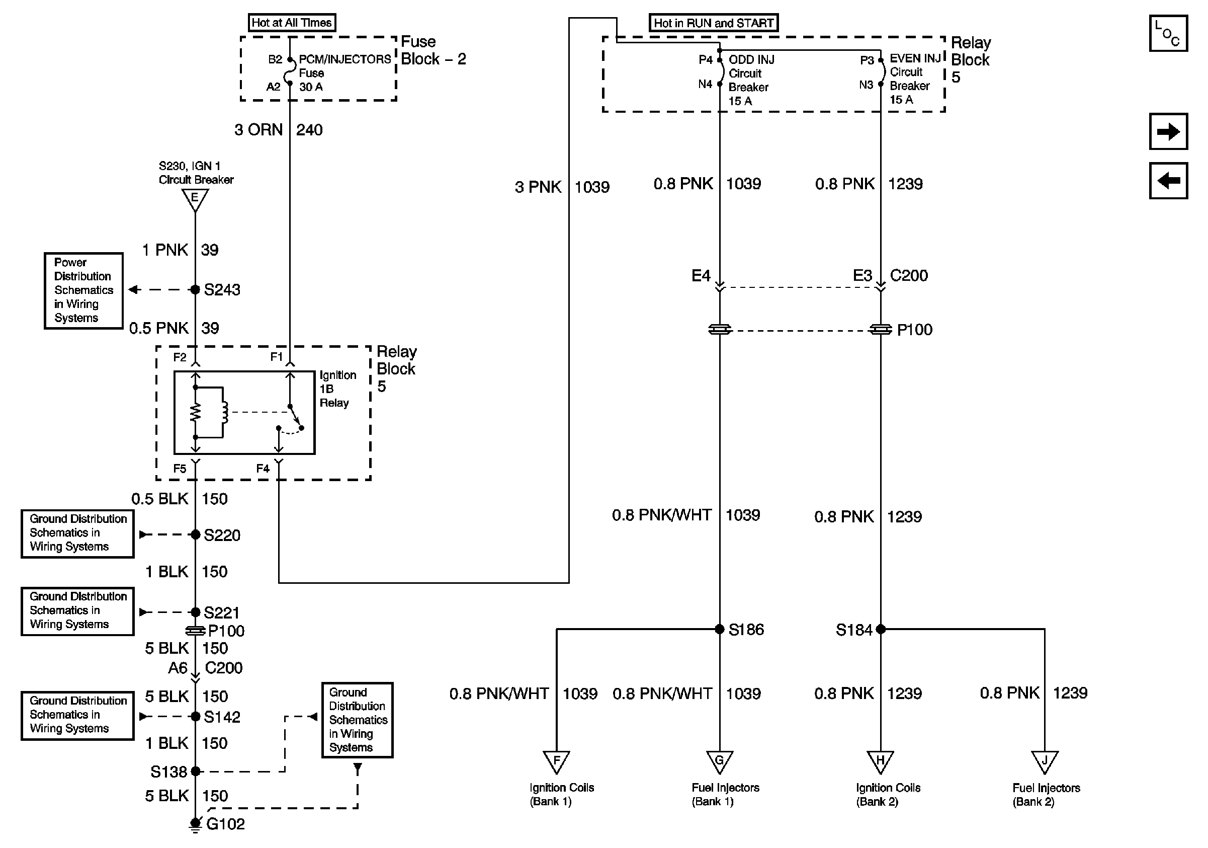
Figure 2:

Power Distribution for Ignition Coils and Fuel Injectors


Object Number: 788274  Size: FS
Master Electrical Component List
Engine Controls Schematics - Indicators
Engine Controls Schematics - Data Link Connector (DLC), Powertrain Control Module (PCM), Power and Ground
Power Distribution Schematics - IGN 1 Circuit Breaker, S232, S243
02Ground Distribution Schematics - G108, and S220 L18
Ground Distribution Schematics - G207, G208, and S221 L18
Ground Distribution Schematics - S142, S178, S179, S405 and S409 L18
Ground Distribution Schematics - G102, and S138 L18
Engine Controls Schematics - Ignition Coils
Engine Controls Schematics - Fuel Enable and Fuel Injectors
Engine Controls Schematics - Ignition Coils
Engine Controls Schematics - Fuel Enable and Fuel Injectors
Figure 3:

5 Volt and Low Reference


Object Number: 788245  Size: FS
Master Electrical Component List
Engine Controls Schematics - Intake Air Temperature (IAT)/Mass Air Flow (MAF) and Manifold Absolute Pressure (MAP) Sensors
Engine Controls Schematics - Power Distribution for Ignition Coils and Fuel Injectors
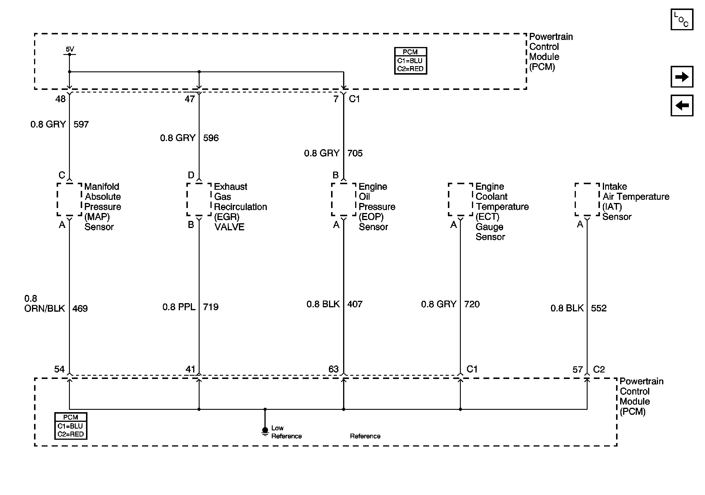
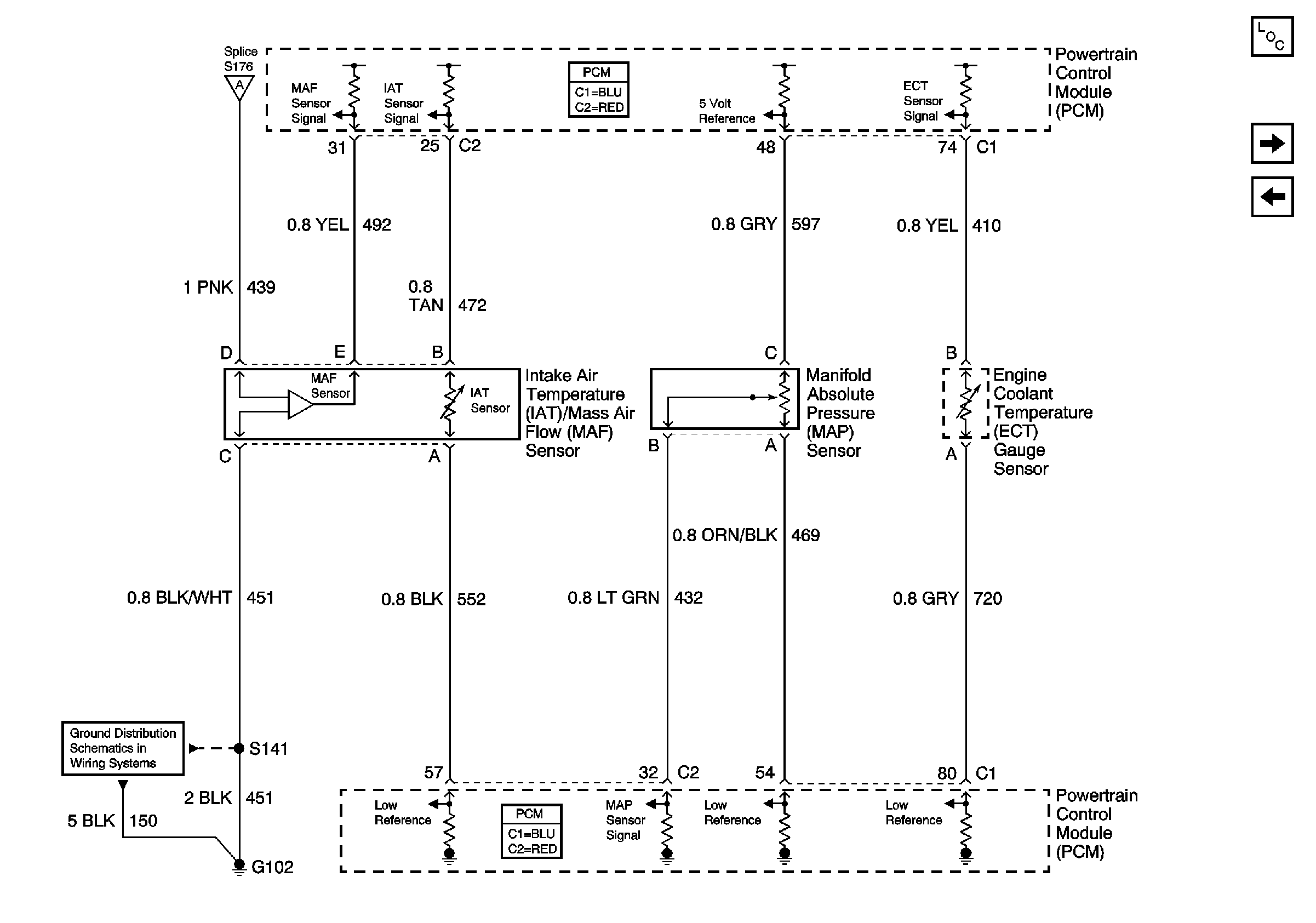
Figure 4:

Intake Air Temperature (IAT)/Mass Air Flow (MAF) and Manifold Absolute Pressure (MAP) Sensors


Object Number: 788278  Size: FS
Master Electrical Component List
Engine Controls Schematics - C212 Upfitter Connector and Vehicle Speed Sensor (VSS)
Engine Controls Schematics - Indicators
Engine Controls Schematics - Data Link Connector (DLC), Powertrain Control Module (PCM), Power and Ground
Ground Distribution Schematics - G102, and S138 L18
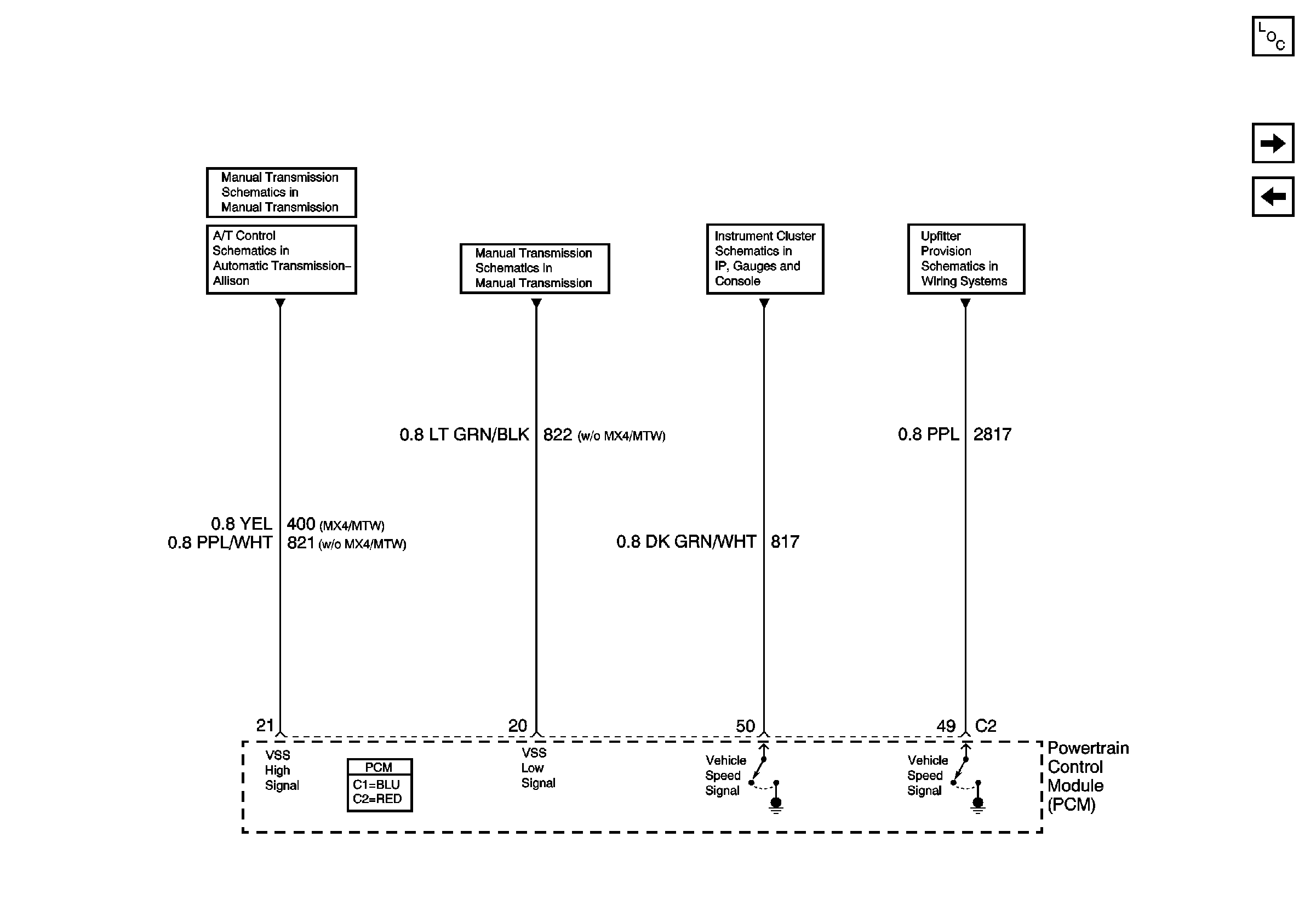
Figure 5:

C212 (Upfitter Connector) and Vehicle Speed Sensor (VSS)

Object Number: 788283  Size: FS
Master Electrical Component List
Engine Controls Schematics - Heated Oxygen Sensors (HO2S)
Engine Controls Schematics - Intake Air Temperature (IAT)/Mass Air Flow (MAF) and Manifold Absolute Pressure (MAP) Sensors
Manual Transmission Schematics - VSS, CPP, TFT
Automatic Transmission Controls Schematics - Data Link Connector (DCL), Powertrain Control Module (PCM), Vehicle Speed Signal
Manual Transmission Schematics - VSS, CPP, TFT
Instrument Cluster Schematics - IPC, Fuel Gage, Gen Chg Ind and Tach
Upfitter Provision Schematics - C212 Upfitter Connector Terminals B, N, P, T and X, Junction Block - Upfitter I/P
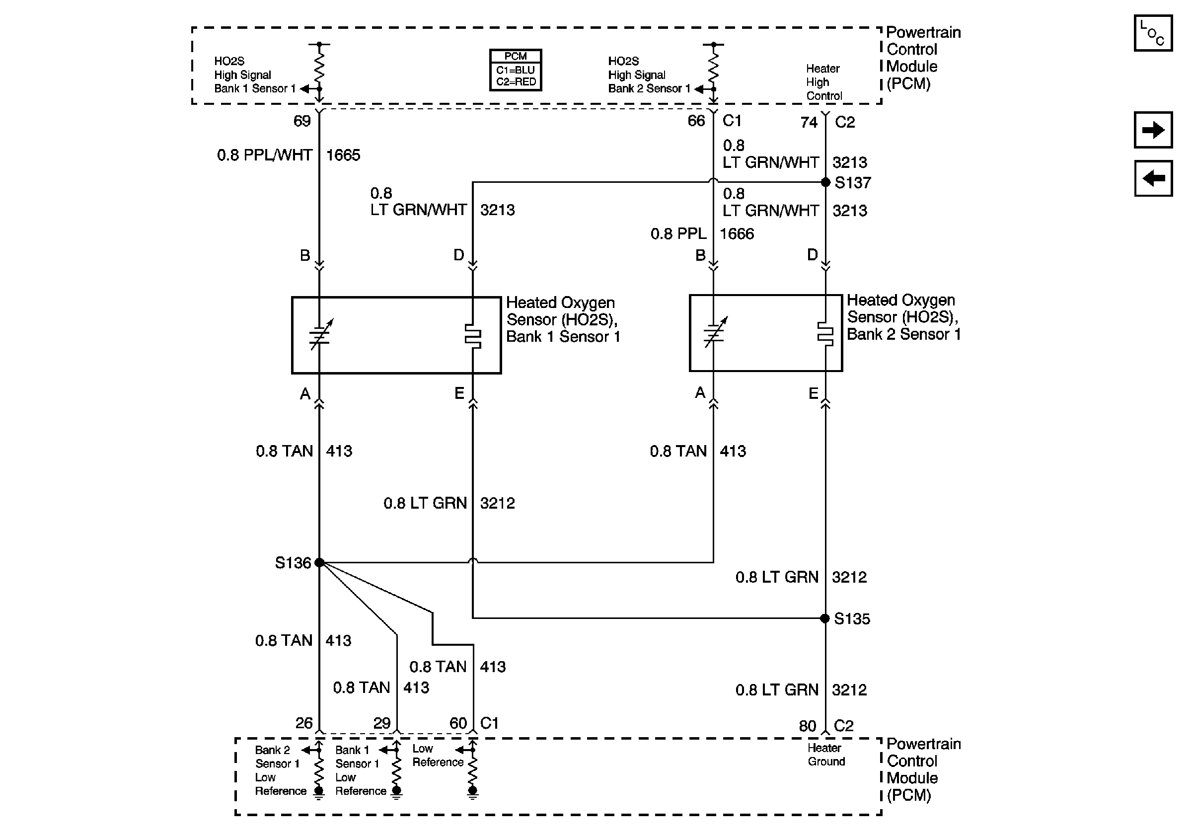
Figure 6:

Heated Oxygen Sensors (HO2S)


Object Number: 788285  Size: FS
Master Electrical Component List
Engine Controls Schematics - Throttle Actuator Control (TAC) Motor, TAC Module and Throttle Position (TP) Sensor
Engine Controls Schematics - C212 Upfitter Connector and Vehicle Speed Sensor (VSS)
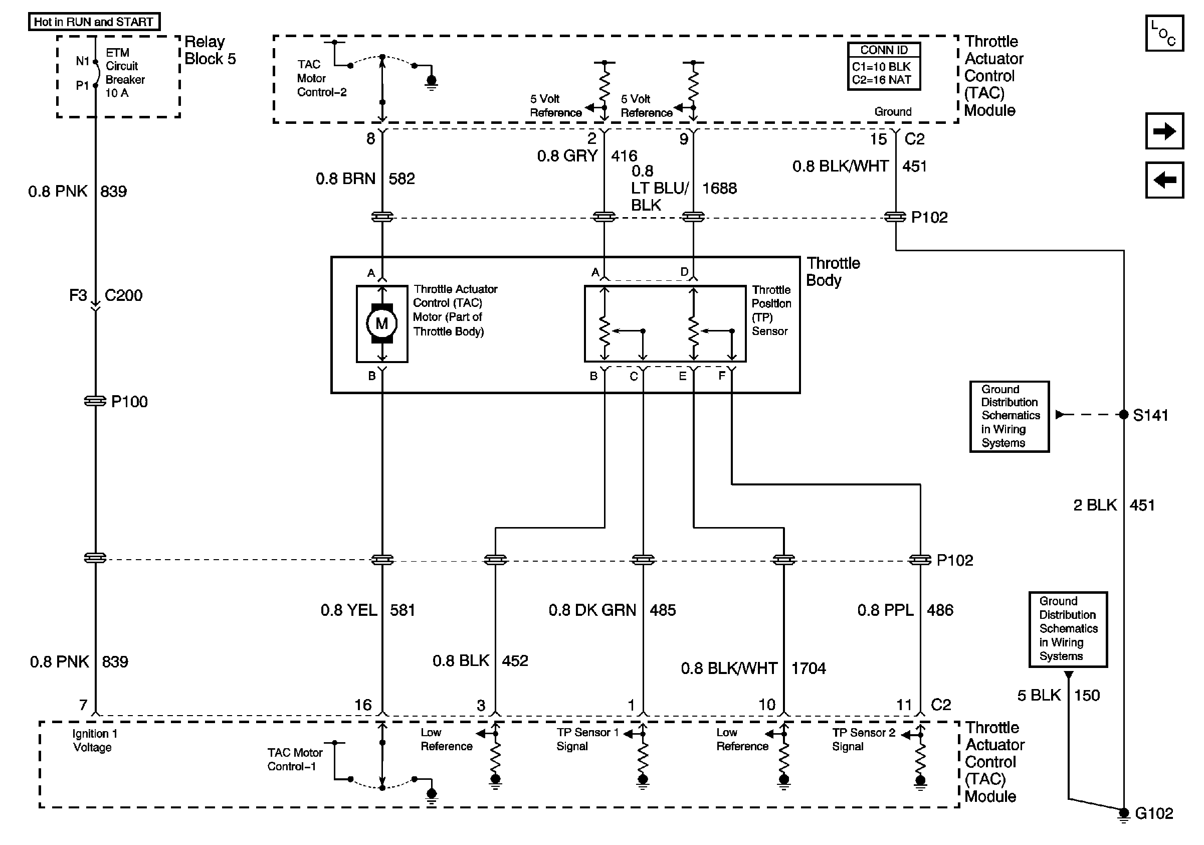
Figure 7:

Throttle Actuator Control (TAC) Motor, TAC Module and Throttle Position (TP) Sensor


Object Number: 788288  Size: FS
Master Electrical Component List
Engine Controls Schematics - Accelerator Pedal and Throttle Actuator Control (TAC)Module
Engine Controls Schematics - Heated Oxygen Sensors (HO2S)
02Ground Distribution Schematics - S141 and S210 L18
Ground Distribution Schematics - G102, and S138 L18
Figure 8:

Accelerator Pedal and Throttle Actuator Control (TAC) Module
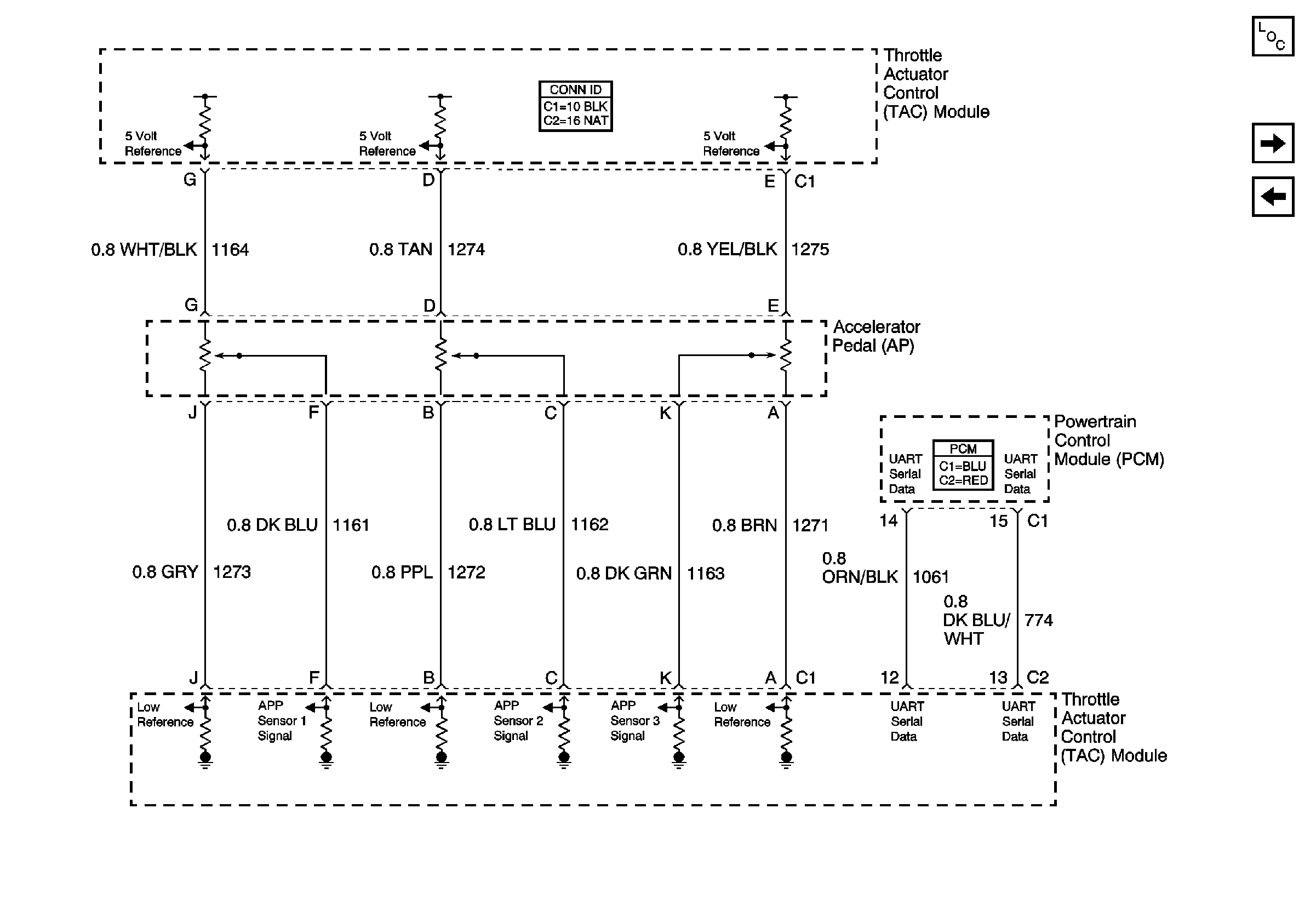

Object Number: 788292  Size: FS
Master Electrical Component List
Engine Controls Schematics - Clutch Pedal Position (CPP), Turn Signal/Multifunction and High Idle Switches and Throttle Actuator Control (TAC) Module
Engine Controls Schematics - Throttle Actuator Control (TAC) Motor, TAC Module and Throttle Position (TP) Sensor
Figure 9:

Clutch Start Switch, Turn Signal/Multifunction and High Idle Switches and Throttle Actuator Control (TAC) Module
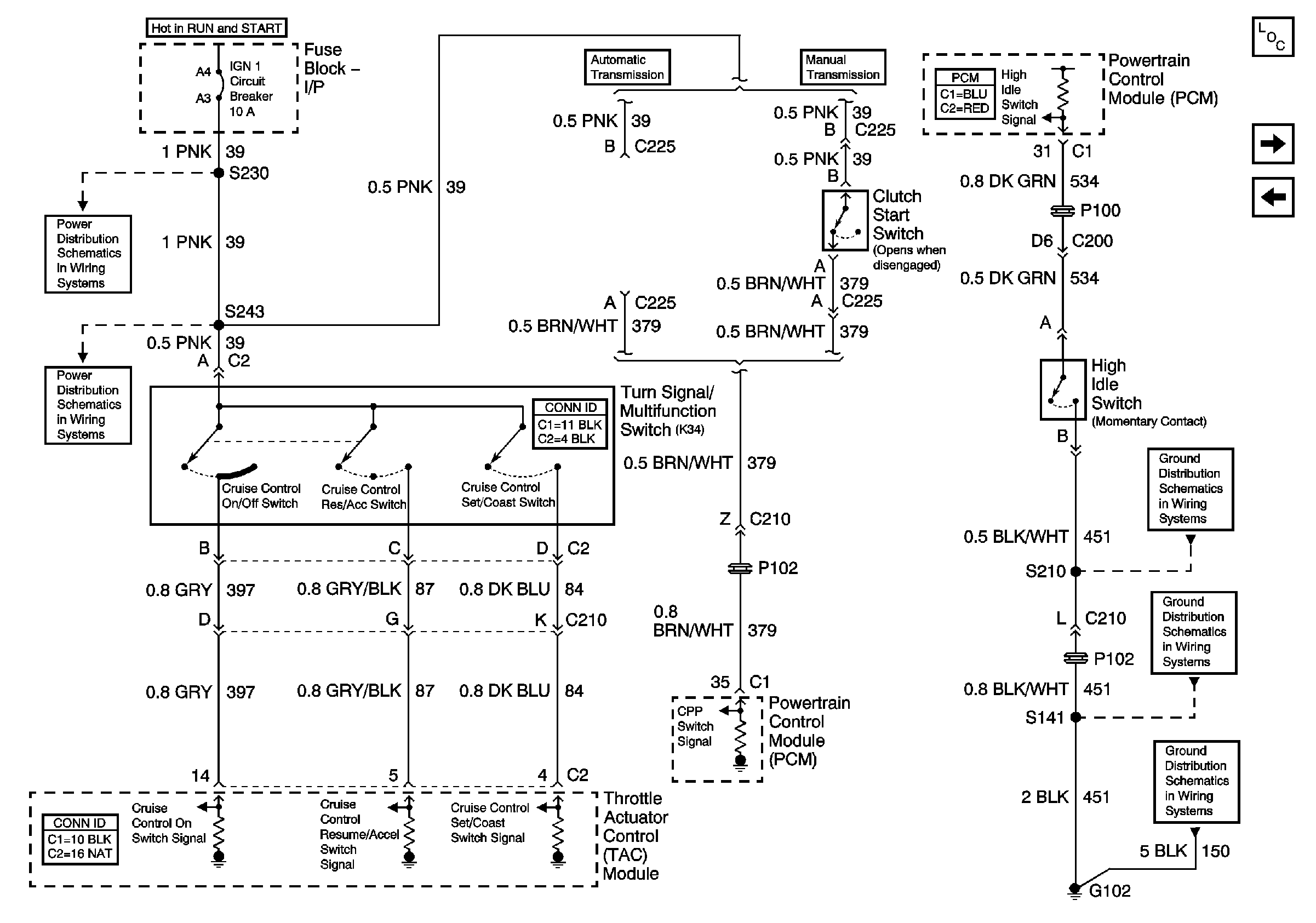

Object Number: 788313  Size: FS
Master Electrical Component List
Engine Controls Schematics - Ignition Coils
Engine Controls Schematics - Accelerator Pedal and Throttle Actuator Control (TAC)Module
02Ground Distribution Schematics - S141 and S210 L18
Ground Distribution Schematics - G102, and S138 L18
Power Distribution Schematics - IGN 1 Circuit Breaker, S225, S226, S230
Power Distribution Schematics - IGN 1 Circuit Breaker, S232, S243
Figure 10:

Ignition Coils


Object Number: 788296  Size: FS
Master Electrical Component List
Engine Controls Schematics - Camshaft Position (CMP) and Crankshaft Position (CKP) Sensors, Knock Sensor (KS) and Tachometer
Engine Controls Schematics - Clutch Pedal Position (CPP), Turn Signal/Multifunction and High Idle Switches and Throttle Actuator Control (TAC) Module
Engine Controls Schematics - Power Distribution for Ignition Coils and Fuel Injectors
Ground Distribution Schematics - S142, S178, S179, S405 and S409 L18
Ground Distribution Schematics - G102, and S138 L18
Figure 11:

Camshaft Position (CMP) and Crankshaft Position (CKP) Sensors, Knock Sensors (KS) and Tachometer
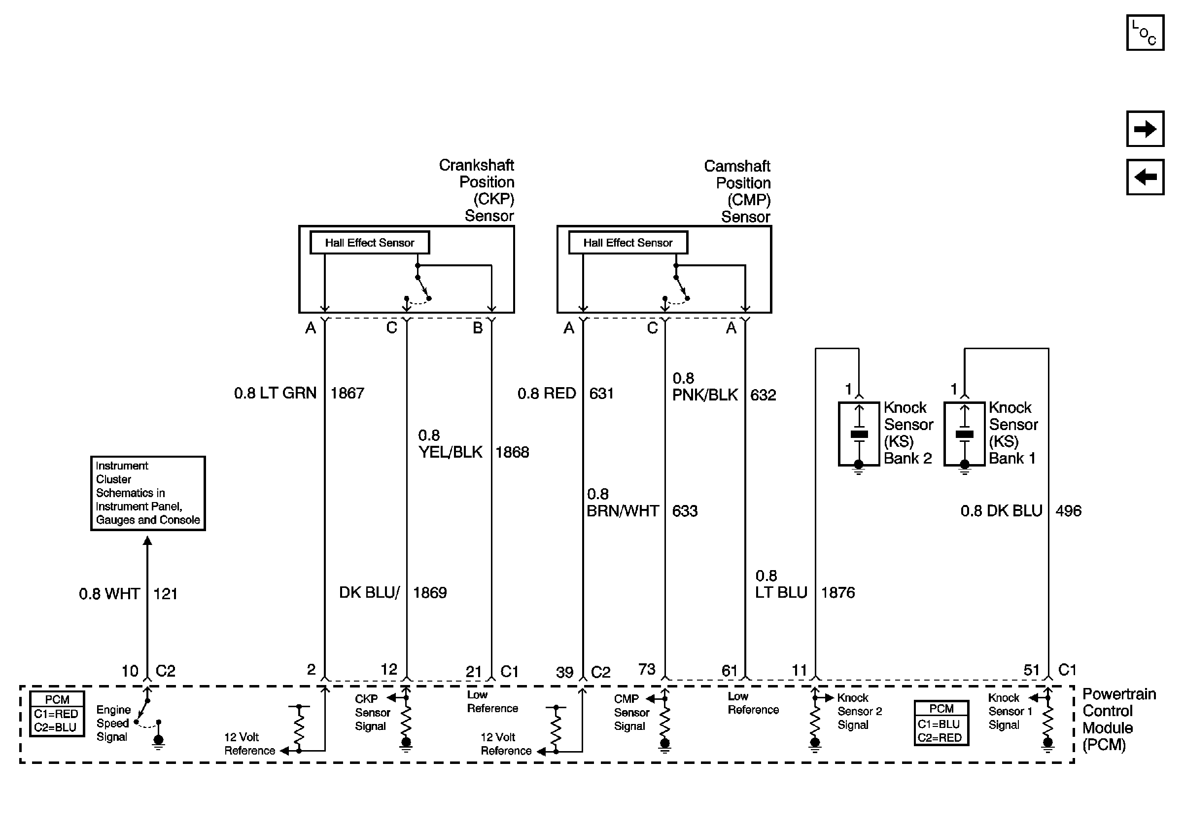

Object Number: 788297  Size: FS
Master Electrical Component List
Engine Controls Schematics - Fuel Enable and Fuel Injectors
Engine Controls Schematics - Ignition Coils
Instrument Cluster Schematics - IPC, Fuel Gage, Gen Chg Ind and Tach
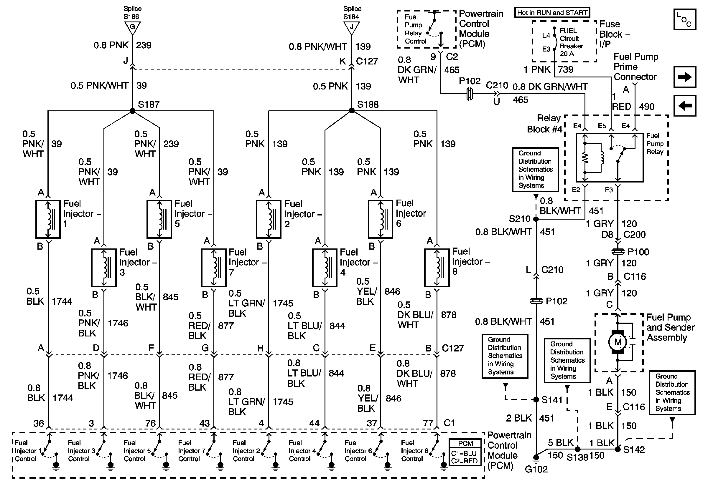
Figure 12:

Fuel Enable and Fuel Injectors


Object Number: 788298  Size: FS
Master Electrical Component List
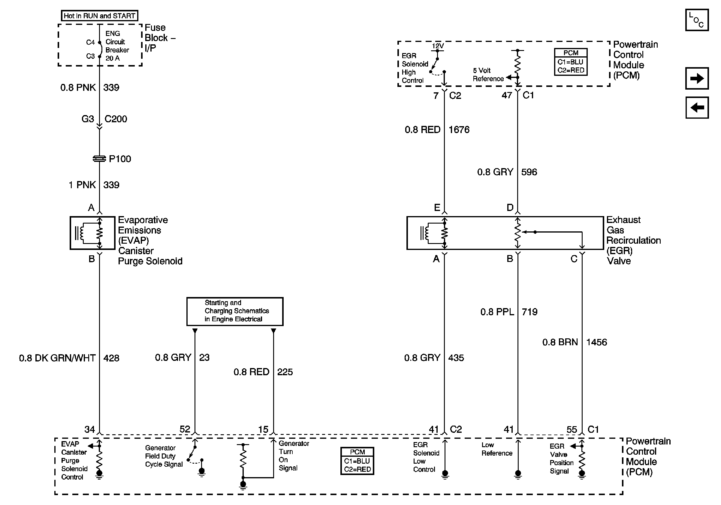
Engine Controls Schematics - Evaporative Emissions (EVAP) Canister Purge Solenoid, Exhaust Gas Recirculation (EGR) Valve, Generator and Generator Charge Indicator
Engine Controls Schematics - Camshaft Position (CMP) and Crankshaft Position (CKP) Sensors, Knock Sensor (KS) and Tachometer
Engine Controls Schematics - Power Distribution for Ignition Coils and Fuel Injectors
02Ground Distribution Schematics - S141 and S210 L18
Ground Distribution Schematics - G102, and S138 L18
Ground Distribution Schematics - S142, S178, S179, S405 and S409 L18
Figure 13:

Evaporative Emissions (EVAP) Canister Purge Solenoid, Exhaust Gas Recirculation (EGR) Valve, Generator and Generator Charge Indicator


Object Number: 788300  Size: FS
Master Electrical Component List
Engine Controls Schematics - Stoplamp Switch and Interface Module, Multifunction Alarm Module, Transmission Control Module (TCM) and C212 Upfitter Connector
Engine Controls Schematics - Fuel Enable and Fuel Injectors
Starting and Charging Schematics - L18 Charging Circuit
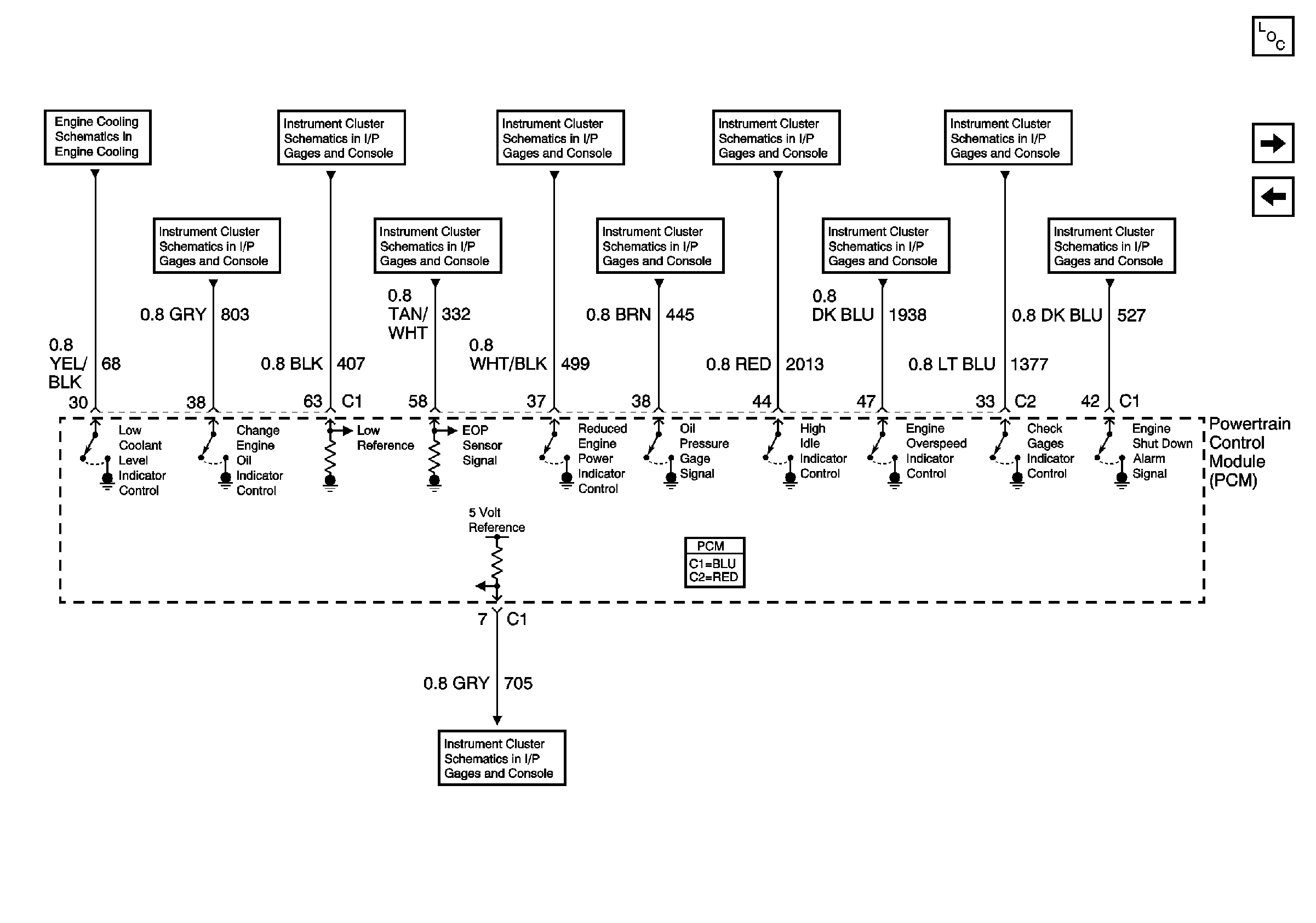
Figure 14:

Instrument Panel Cluster References


Object Number: 788301  Size: FS
Master Electrical Component List
Engine Controls Schematics - Clutch, Park /Neutral Position (PNP) and Neutral Safety Switches, Starter Relay and Transmission Control Module (TCM)
Engine Controls Schematics - Heated Oxygen Sensors (HO2S)
Engine Cooling Schematics - Driver Information Center (DIC), Multifunction Alarm Module, Coolant Level Switch
Instrument Cluster Schematics - DIC, AUX and PB, and Check Trans
Instrument Cluster Schematics - DIC, ABS, CHG OIL, DRL, EOS and HI Ind.
Instrument Cluster Schematics - IPC, Check Ind, ECT, and EOP Gages
Instrument Cluster Schematics - DIC, ABS, CHG OIL, DRL, EOS and HI Ind.
Instrument Cluster Schematics - DIC, AUX and PB, and Check Trans
Instrument Cluster Schematics - IPC, Check Ind, ECT, and EOP Gages
Instrument Cluster Schematics - DIC, ABS, CHG OIL, DRL, EOS and HI Ind.
Instrument Cluster Schematics - IPC, High Beam, LT and RT Ind, I/P ILL
Instrument Cluster Schematics - IPC, Check Ind, ECT, and EOP Gages
Charging Circuit
Figure 15:

Automatic Transmission and Manual Transmission References
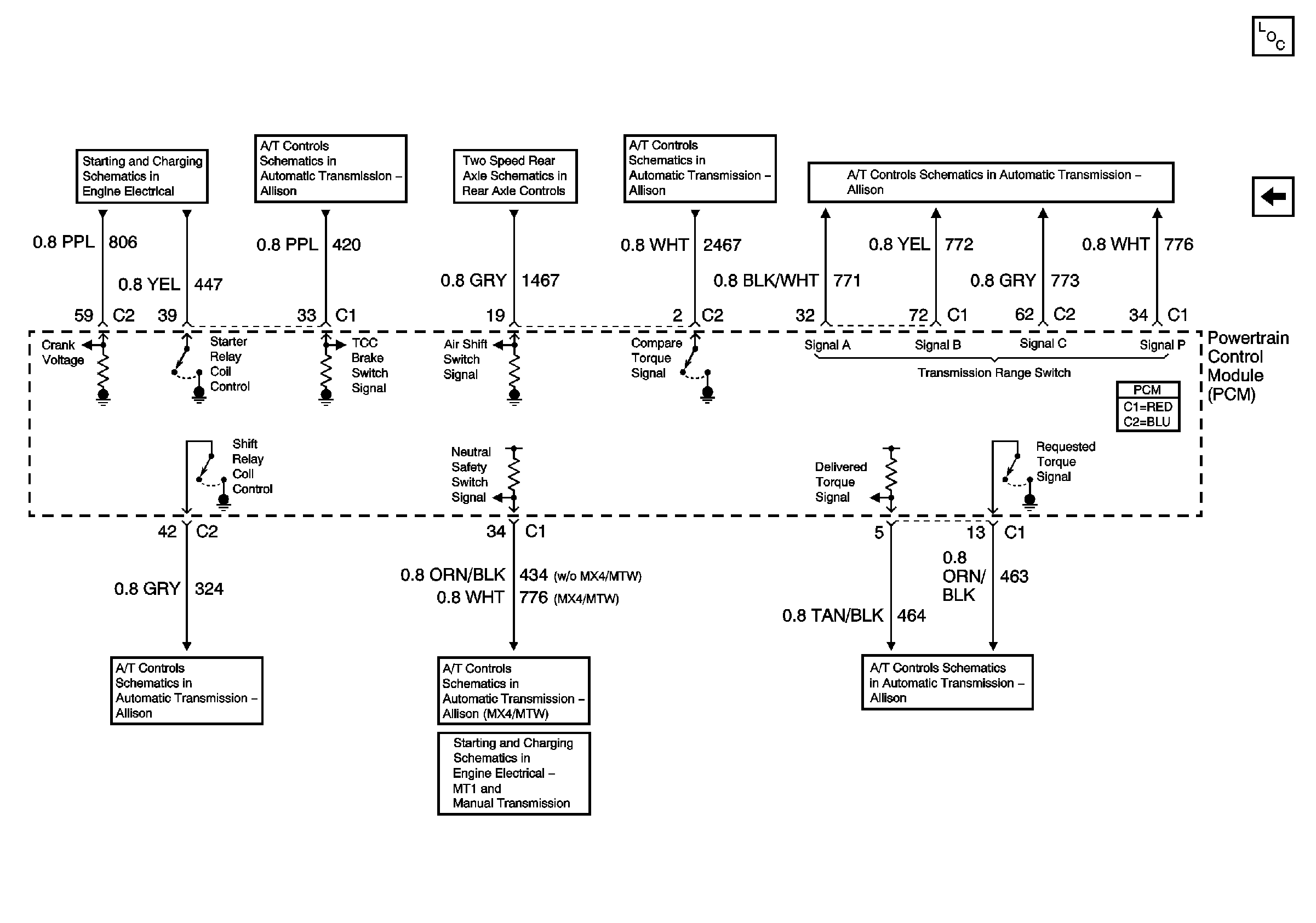

Object Number: 788302  Size: FS
Master Electrical Component List
Engine Controls Schematics - Stoplamp Switch and Interface Module, Multifunction Alarm Module, Transmission Control Module (TCM) and C212 Upfitter Connector
Starting and Charging Schematics - L18 Starting Circuit
Automatic Transmission Schematics - TCM, Stop Lamp SW Interface Module
Two Speed Rear Axle Schematics
Automatic Transmission Controls Schematics - Speed and Sump Temperature Sensors and Trans I.D. (MX4/MTW)
Automatic Transmission Controls Schematics - Internal Pressure Switch and Solenoids (MX4/MTW)
Automatic Transmission Schematics - A/T Modulator and Relay
Starting and Charging Schematics - L18 Starting Circuit
Automatic Transmission Controls Schematics - Internal Pressure Switch and Solenoids (MX4/MTW)