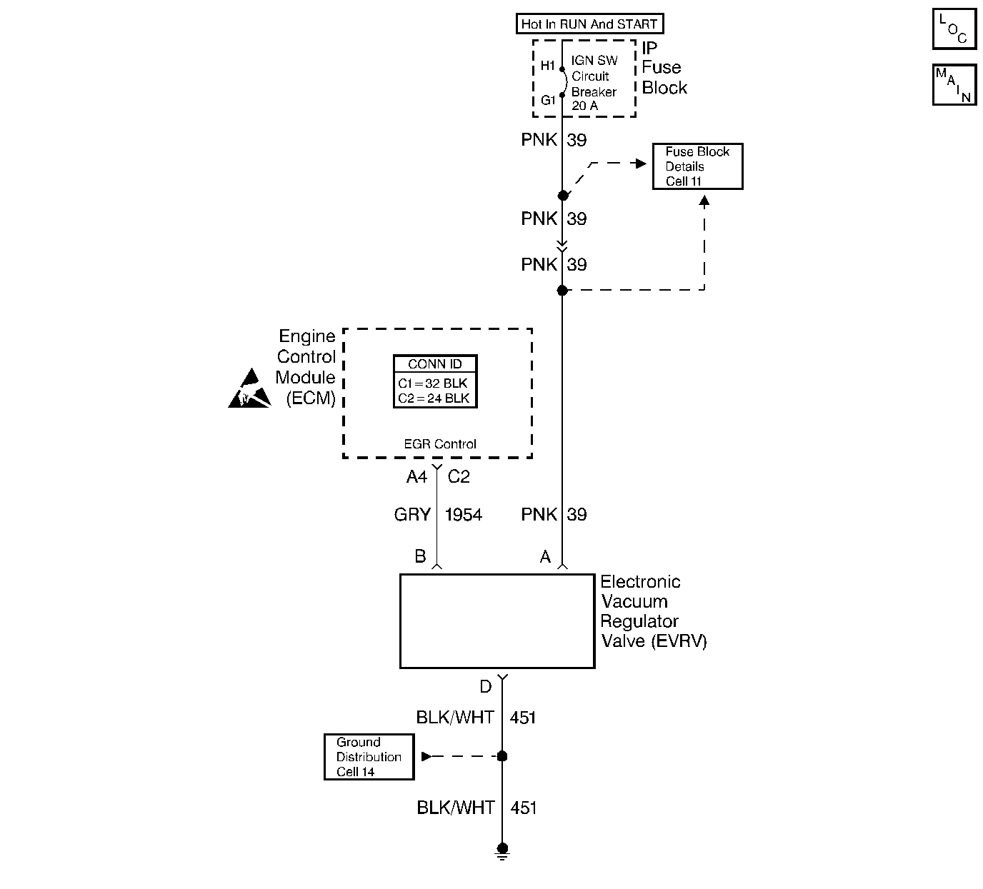
Circuit Description
The ECM operates a solenoid in order to control the Exhaust Gas Recirculation (EGR) valve. This solenoid is normally closed. By providing a ground path, the ECM energizes the solenoid which allows the vacuum to pass to the EGR valve.
Conditions for Setting the DTC
The ECM monitors the EGR effectiveness by de-energizing the EGR control solenoid shutting OFF vacuum to the EGR valve diaphragm. With the EGR valve closed, the fuel integrator counts will be greater than they were during the normal EGR operation. If the change is not within the calibrated window, a DTC 32 will be set.
The ECM will check the EGR operation when:
| • | The engine vacuum is between 40 and 51 kPa. |
| • | The TP signal is between 5% and 60% with no change in throttle position while the test is running. |
| • | The engine speed is above 2,000 RPM. |
| • | The EGR duty cycle is above 50%. |
Action Taken When the DTC Sets
The Malfunction Indicator Lamp (MIL) will illuminate.
Conditions for Clearing the MIL/DTC
The conditions for the fault are no longer present and 50 ignition cycles have passed with no further faults or the ignition switch is turned OFF and the battery feed voltage is removed for 10 seconds.
Diagnostic Aids
The electrical check cannot diagnose the EVRV solenoid because of the solid state circuitry involved.
Check the vacuum lines thoroughly for proper routing. Refer to Vehicle Emission Control Information Label located on engine air cleaner.
Test Description
The numbers below refer to the step numbers on the Diagnostic Table.
-
With the ignition ON and the engine OFF, the solenoid should not be energized and the vacuum should not pass to the EGR valve. Grounding the diagnostic terminal will energize the solenoid and allow the vacuum to pass to EGR valve.
-
Checks for plugged EGR passages. If passages are plugged, the engine may have severe detonation on acceleration.
-
Drive the vehicle must be driven during this test in order to produce sufficient engine load in order to operate the EGR. Lightly accelerating (approximately 1/4 throttle) will produce a large and stable enough reading in order to determine if the ECM is commanding the system ON.
Step | Action | Value(s) | Yes | No |
|---|---|---|---|---|
1 | Did you perform the On-Board Diagnostic (OBD) System Check? | -- | ||
Does the EGR valve move? | -- | |||
Does the idle roughen? | -- | |||
Is the EGR vacuum less than the specified value? | 34 kpa (10 in Hg) | Go to Intermittent Conditions | ||
5 |
Did you find a problem? | -- | ||
6 | Replace the EGR filter. Refer to Exhaust Gas Recirculation Filter Cleaning/Replacement . Is the action complete? | -- | -- | |
7 |
Is the lamp ON? | -- | ||
8 | Connect a J 35616-200 unpowered test lamp between the ignition feed and the EVRV solenoid assembly ground circuit. Is the lamp ON? | -- | ||
9 |
Is the test lamp ON? | -- | ||
10 | Replace the EVRV solenoid. Refer to EVRV Solenoid Replacement . Is the action complete? | -- | -- | |
11 | Replace the EGR valve. Refer to Exhaust Gas Recirculation Valve Replacement . Is the action complete? | -- | -- | |
12 | Repair the open in the ignition feed circuit. Refer to Wiring Repairs in Wiring Systems. Is the action complete? | -- | -- | |
13 | Repair the open in the ground circuit. Refer to Wiring Repairs in Wiring Systems. Is the action complete? | -- | -- | |
14 |
Did you find a problem? | -- | ||
15 | Replace the ECM. Refer to Engine Control Module Replacement . Is the action complete? | -- | -- | |
16 |
Did the DTC reset? | -- | ||
17 | Are any DTCs stored which you have not diagnosed? | -- | Go to the Applicable DTC Table | System OK |
