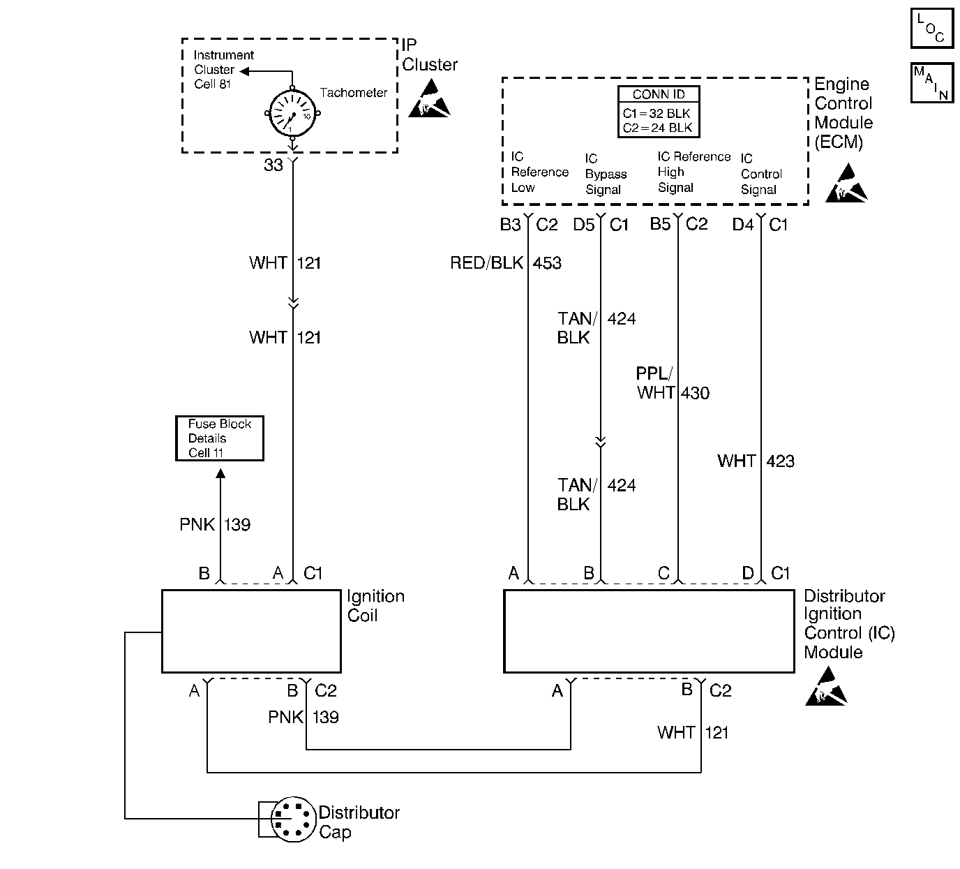
Circuit Description
When the system runs on the Ignition Control (IC) module, no voltage on the IC bypass circuit, the ignition control module grounds the IC control circuit.
When the system reaches about 400 RPM, and the system applies the bypass voltage, the IC control will no longer be grounded in the ignition control module so the IC control voltage will vary.
Conditions for Setting the DTC
| • | The system running on the IC module |
| • | No voltage on the bypass circuit |
| • | IC module grounding the IC control circuit |
| • | ECM detects voltage on the IC control circuit |
| Or |
| • | IC bypass circuit is open or grounded, the ignition module will not switch to IC mode so the IC voltage will be low. |
| Or |
| • | The IC control line is grounded, the ignition control module will switch to IC, but because the circuit is grounded there will be no IC signal. A DTC 42 will be set. |
Action Taken When the DTC Sets
The Malfunction Indicator Lamp (MIL) will illuminate. The system will go Open Loop.
Conditions for Clearing the MIL/DTC
The conditions for the fault are no longer present and 50 ignition cycles have passed with no further faults or the ignition switch is turned OFF and the battery feed voltage is removed for 10 seconds.
Diagnostic Aids
The scan tool does not have any ability to help diagnose a DTC 42 problem.
Refer to Intermittent Conditions .
Test Description
The numbers below refer to the step numbers on the Diagnostic Table.
-
A DTC 42 means the ECM has seen an open or short to ground in the IC control or bypass circuits. This test confirms DTC 42 and that the fault causing the DTC is present.
-
This step checks for a normal IC ground path through the ignition control module. An IC control circuit shorted to ground will also read less than 500 ohms; however, this will be checked later.
-
As the test light voltage touches IC bypass circuit, the ignition control module should switch causing the ohmmeter to over-range if the meter is in the 100-200 ohms position. Selecting the 10-20,000 ohms position will indicate above 5,000 ohms. The important thing is that the module switched.
-
This step confirms that a DTC 42 is a faulty ECM and not an intermittent in IC reference and IC bypass circuit.
-
If the module did not switch, this step checks for the following items:
| • | IC control circuit shorted to ground |
| • | Bypass circuit open |
| • | Faulty ignition control module connection or module |
Step | Action | Value(s) | Yes | No |
|---|---|---|---|---|
1 | Did you perform the On-Board Diagnostic (OBD) System Check? | -- | ||
Does a DTC 42 set? | -- | Go to Diagnostic Aids | ||
Is the resistance less than the specified value? | 1,000 ohms | |||
4 |
Did you find a problem? | -- | ||
5 |
Did you find a problem? | -- | ||
6 | Probe the ECM connector at the IC bypass circuit with a J 35616-200 unpowered test light to B+. Is the test light ON? | -- | ||
With the J 39200 still connected to the ECM harness IC control circuit and a ground, again probe the ECM harness IC bypass circuit with a J 35616-200 unpowered test lamp connected to B+. Observe the resistance as the test lamp contacts the IC bypass circuit. Does the resistance switch from less than to greater than the specified values? | 1,000-2,000 ohms | |||
Does the DTC 42 set? | -- | Go to Diagnostic Aids | ||
With J 39200 still connected to the IC control circuit and a ground, disconnect the distributor 4 way connector. Does the resistance indicate an open circuit? | -- | |||
10 |
Did you find a problem? | -- | ||
11 | Repair the IC control circuit shorted to ground. it. Refer to Wiring Repairs in Wiring Systems. Is the action complete? | -- | -- | |
12 |
Did you find a problem? | -- | ||
13 | Disconnect the DI control module 4 way connector. Does the J 35616-200 test lamp stay ON? | -- | ||
14 | Repair the short to ground in the IC bypass circuit. Refer to Wiring Repairs in Wiring Systems. Is the action complete? | -- | -- | |
15 | Replace the distributor ignition (DI) control module. Refer to Distributor Replacement . Is the action complete? | -- | -- | |
16 | Replace the ECM. Refer to Engine Control Module Replacement . Is the action complete? | -- | -- | |
17 |
Did the DTC reset? | -- | ||
18 | Are any DTCs stored which you have not diagnosed? | -- | Go to the Applicable DTC Table | System OK |
