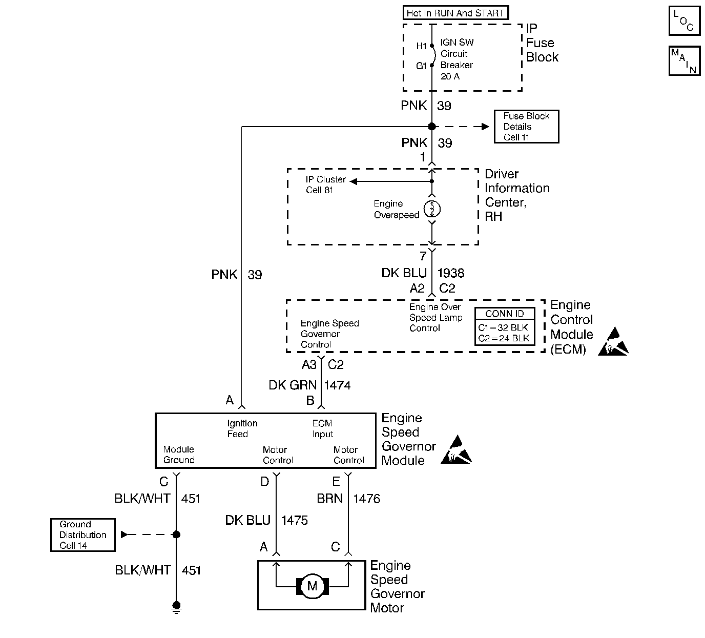
Circuit Description
The ECM sends a pulse width modulated signal, via the engine speed governor control circuit, to the engine speed governor module to drive the governor motor.
Depending on the amount of governing required, the module translates the ECM data into the appropriate value of DC current to the motor, which pulls back on the throttle to correct the overspeed condition. The system is capable of holding the throttle at an idle (100 percent authority).
The ECM controls of the engine speed governor system is based on engine speed (RPM).
A DTC 31 will detect a faulty ECM, a governor module, a motor, a linkage, or wiring.
Conditions for Setting the DTC
| • | ECM commands near 100% authority. |
| • | Engine RPM higher than calibrated governed speed. |
Action Taken When the DTC Sets
The Malfunction Indicator Lamp (MIL) will illuminate, and the ECM will limit the engine and the vehicle speed by momentarily reducing fuel.
Conditions for Clearing the MIL/DTC
The conditions for the fault are no longer present and 50 ignition cycles have passed with no further faults or the ignition switch is turned OFF and the battery feed voltage is removed for 10 seconds.
Diagnostic Aids
Before replacing the ECM, use the J 39200 and check the resistance of each ECM controlled relay and solenoid coil.
Refer to Engine Controls Schematics for coil terminal identification of solenoids and relays to be checked. Replace any relay or solenoid where the coil resistance measures less than 20 ohms.
Refer to Intermittent Conditions .
Test Description
The numbers below refer to the step numbers on the Diagnostic Table.
-
This step determines if the governor module has a supply voltage with which to operate.
-
Applying +12 volts to the motor determines the motor, the wiring, and the linkage integrity. Do not hold current to the motor for longer than 30 seconds because damage to the motor could result.
-
This test will command 100 percent (full) governing in order to determine if the ECM or the engine speed governor system is at fault.
Step | Action | Value(s) | Yes | No |
|---|---|---|---|---|
1 | Did you perform the On-Board Diagnostic (OBD) System Check? | -- | ||
Is the test lamp ON? | -- | |||
3 | Repair the open in the ignition feed circuit. Refer to Wiring Repairs in Wiring Systems. Is the action complete? | -- | -- | |
4 | Connect a J 35616-200 unpowered test lamp between the ignition feed circuit and the ground circuit of the harness connector. Is the test lamp ON? | -- | ||
5 | Repair the open ground circuit. Refer to Wiring Repairs in Wiring Systems. Is the action complete? | -- | -- | |
Will the engine accelerate? | 30 seconds | |||
7 |
Did you find a problem? | -- | ||
8 |
Did you find a problem? | -- | ||
9 |
Did you find a problem? | -- | ||
Will the engine accelerate? | -- | |||
11 |
Did you find a problem? | -- | ||
12 | Replace the engine speed governor control module. Refer to Engine Speed Governor Module Replacement . Is the action complete? | -- | -- | |
13 | Replace the governor motor. Refer to Governor Drive Motor Replacement . Is the action complete? | -- | -- | |
14 | Replace the ECM. Refer to Engine Control Module Replacement . Is the action complete? | -- | -- | |
15 |
Did the DTC reset? | -- | ||
16 | Does the scan tool display any additional, undiagnosed DTCs? | -- | Go to the Applicable DTC Table | System OK |
