Product Safety - Steering Linkage Bearing Ball Socket

| Subject: | 01030 -- Steering Linkage Bearing Ball Socket |
| Models: | 1999-2000 Chevrolet and GMC C-Series, T-Series and B-Series Vehicles |
Condition
General Motors has decided that a defect which relates to motor vehicle safety exists in certain 1999-2000 Chevrolet and GMC C-Series, T-Series and B-Series vehicles. Some of these vehicles have a condition in which the bearing ball sockets in the tie rods and/or the relay rod may not have been manufactured to the print specification for case depth and hardness, resulting in the potential for premature wear-out and eventual joint separation. As the joint wears, the driver may notice a loose, on-center steering feel. If the vehicle continued to be operated in this condition, a tie rod or relay rod joint could separate from the socket. If a tie rod were to separate, vehicle control could still be maintained; however, there would be noticeable steering vagueness, and the vehicle would have a tendency to wander. If a relay rod socket were to separate, steering control would be lost and a vehicle crash could occur without prior warning.
Correction
Dealers are to inspect and replace all tie rod ends and/or relay rods that have the suspect socket date codes.
Vehicles Involved
Involved are certain 1999-2000 Chevrolet and GMC C-Series, T-Series and B-Series vehicles. Dealers should confirm vehicle eligibility through GMVIS (GM Vehicle Inquiry System) or GM Access Screen (Canada only) or DCS Screen 445 (IPC Only) before beginning campaign repairs.
Involved vehicles have been identified by Vehicle Identification Number. Computer listings containing the complete Vehicle Identification Number, customer name and address data have been prepared, and are being furnished to involved dealers with the campaign bulletin. The customer name and address data furnished will enable dealers to follow-up with customers involved in this campaign. Any dealer not receiving a computer listing with the campaign bulletin has no involved vehicles currently assigned.
These dealer listings may contain customer names and addresses obtained from Motor Vehicle Registration Records. The use of such motor vehicle registration data for any other purpose is a violation of law in several states/provinces/countries. Accordingly, you are urged to limit the use of this listing to the follow-up necessary to complete this campaign.
Parts Information
Parts required to complete this campaign are to be obtained from General Motors Service Parts Operations (GMSPO). Please refer to your "involved vehicles listing" before ordering parts. Normal orders should be placed on a DRO = Daily Replenishment Order. In an emergency situation, parts should be ordered on a CSO = Customer Special Order.
P/N | Description | Models | Qty/Vehicle |
|---|---|---|---|
15986858 | Rod, Strg Lnkg Rly | C6/7 with FL1/FL2 and JE3 and N40 | 1 (If Req'd) |
B-Series with N40 | |||
15986859 | Rod, Strg Lnkg Rly | C6/7 with FL1/FL2 and JE4and N40 | 1 (If Req'd) |
15986856 | Rod, Strg Lnkg Rly | C7 with FL2 and NXW | 1 (If Req'd) |
C7 with FS7 and JE3 and NXW | |||
B-Series with NXW | |||
15986855 | Rod, Strg Lnkg Rly | C7 with FL3 and NXW | 1 (If Req'd) |
C7 with FS7 and JE4 and NXW | |||
15983440 | Rod, Strg Lnkg Rly | T-Series | 1 (If Req'd) |
12548110 | End, Strg Lnkg Tie Rod (LH) | C7 with FL1 | 1 (If Req'd) |
T-Series with FL1 | |||
B-Series with FL1 | |||
12548111 | End, Strg Lnkg Tie Rod (RH) | C7 with FL1 | 1 (If Req'd) |
T-Series with FL1 | |||
B-Series with FL1 | |||
11076431 | Pin, Cotter (2 for the relay rod; 1 for each tie rod end) | All Models | As Req'd |
Service Procedure
Model & RPOs | Inspect Tie Rod Ends | Inspect Relay Rod Ends |
|---|---|---|
C Series with FL1 | X | X |
C Series with FL2/FL3/FS7 |
| X |
T Series with FL1 | X | X |
T Series without FL1 |
| X |
B Series with FL1 | X | X |
B Series with F43/FM6 |
| X |
- Refer to the table above to determine what components need to be inspected.
- Measure the outside swage diameter of the appropriate ball socket(s) indicated in the chart above, and record the date code (2) shown on the end cover (1) of the ball sockets as determined above.
- Compare the date codes on the ball sockets to the date codes listed below.
- If the date code DOES NOT match any of the date codes above, no further action is required. Install the GM Campaign Identification Label.
- If the date code matches any of the date codes above, replace only the component(s) with the suspect date code. Follow the appropriate procedure(s) listed below.
Important: Check both ends of the tie rod and the relay rod.
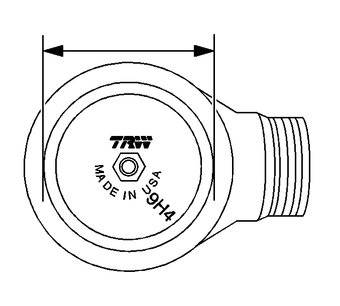
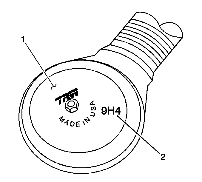
20 Size Socket - outside swage diameter approx. 48mm (1-7/8 in) : 9G1, 9G2, 9G3, 9G4, 9H1, 9H2, 9H3, 9H4, 9H5, 9J1, 9J2, 9J3, 9J4
24 Size Socket - outside swage diameter approx. 54mm (2-1/8 in) : 9G2, 9G3
Relay Rod Replacement Procedure
B and C Series Vehicles
Tools Required
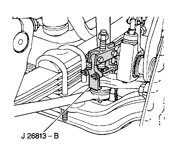
J 26813-B Steering Linkage Puller
Relay Rod Removal Procedure
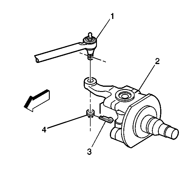
- Position the front wheels and the steering wheel straight ahead.
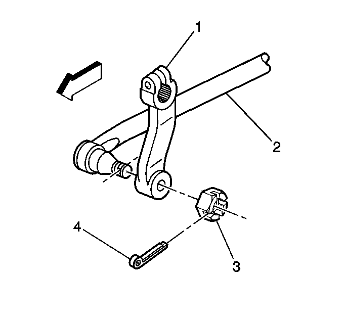
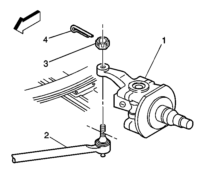
- Remove and discard the cotter pin (4).
- Remove and discard the relay rod/pitman arm nut (3).
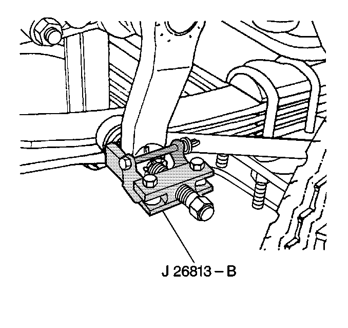
- Use the J 26813-B in order to remove the relay rod from the pitman arm.
- Remove and discard the cotter pin (3).
- Remove and discard the relay rod/steering arm nut (4).
- Use the J 26813-B in order to remove the relay rod from the steering arm.
Relay Rod Installation Procedure
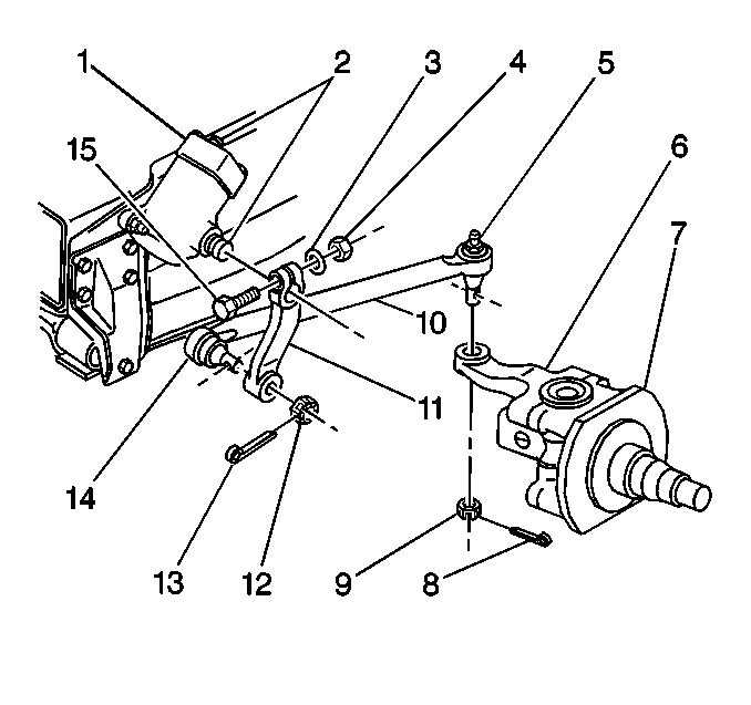
- Install the relay rod (2) ball joint-pitman arm end to the pitman arm (1).
- Install the new pitman arm/relay rod nut (3).
- Install the relay rod (1) ball joint steering arm end to the steering arm.
- Install the new steering arm/relay rod nut (4).
- Advance the relay rod nuts (9, 12) to the nearest cotter pin slot.
- Tighten the relay rod ball joint nuts (9, 12).
- Install the new cotter pins.
- Lubricate the relay rod with chassis lubricant. Refer to Fluid and Lubricant Recommendations and Maintenance Schedule in the Maintenance and Lubrication sub-section of the appropriate Service Manual.
- Install the GM Campaign Identification Label or, if necessary, proceed to the Tie Rod Replacement Procedure below.


Important: Do not back off a relay rod nut in order to insert a cotter pin.
Notice: Use the correct fastener in the correct location. Replacement fasteners must be the correct part number for that application. Fasteners requiring replacement or fasteners requiring the use of thread locking compound or sealant are identified in the service procedure. Do not use paints, lubricants or corrosion inhibitors on fasteners or fastener joint surfaces unless specified. These coatings affect fastener torque and joint clamping force and may damage the fastener. Use the correct tightening sequence and specifications when installing fasteners in order to avoid damage to parts and systems.
Tighten
Tighten the nuts to 129 N·m (95 lb ft) on
the 20 size socket, and 159 N·m (117 lb ft) on
the 24 size socket.
Relay Rod Replacement Procedure
T Series Vehicles
| • | J 24319-01 Steering Linkage Puller |
| • | J 26813-B Steering Linkage Puller |
Relay Rod Removal Procedure
- Position the front wheels and the steering wheel straight ahead.
- Tilt the cab. Refer to Cab Tilting in the General Information sub-section of the Service Manual.
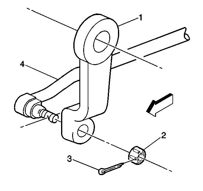
- Remove and discard the cotter pins (3) at each end of the relay rod (4).
- Remove and discard the relay rod nuts (2).
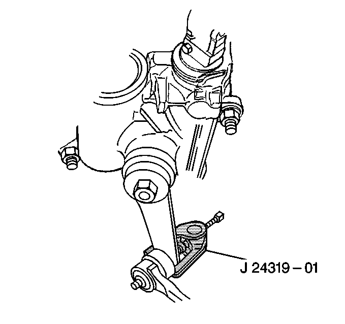
- Use the J 24319-01 in order to remove the relay rod (4) from the pitman arm (1).
- Use the J 26813-B in order to remove the relay rod from the steering arm.
Relay Rod Installation Procedure
- Install the relay rod end assembly (4) to the pitman arm (1).
- Install the new relay rod nut (2).
- Install the relay rod (1) ball joint steering arm end to the steering arm.
- Install the new steering arm/relay rod nut (4).
- Install the relay rod end assembly to the steering arm (1).
- Install the relay rod nut (3).
- Advance the nuts to the nearest cotter pin slot.
- Install the new cotter pins (4).
- Lower the cab.
- Lubricate the relay rod with chassis lubricant. Refer to the appropriate procedure in the Maintenance and Lubrication sub-section of the Service Manual.
- Install the GM Campaign Identification Label or, if necessary, proceed to the Tie Rod Replacement Procedure below.


Notice: Use the correct fastener in the correct location. Replacement fasteners must be the correct part number for that application. Fasteners requiring replacement or fasteners requiring the use of thread locking compound or sealant are identified in the service procedure. Do not use paints, lubricants or corrosion inhibitors on fasteners or fastener joint surfaces unless specified. These coatings affect fastener torque and joint clamping force and may damage the fastener. Use the correct tightening sequence and specifications when installing fasteners in order to avoid damage to parts and systems.
Tighten
Tighten the nut to 160 N·m (120 lb ft).
Tie Rod Replacement Procedure
All Models
Tools Required
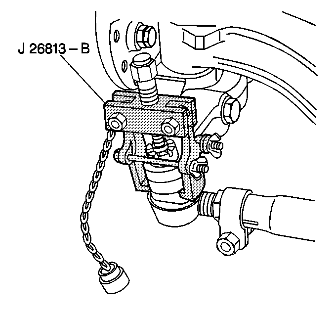
J 26813-B Steering Linkage Puller
Tie Rod Removal Procedure
- Note the following before beginning repairs to the tie rod assembly:
- Remove and discard the cotter pin (2) from the tie rod end ball joint (7).
- Remove and discard the nut (1) from the tie rod ball joint (7).
- Use the J 26813-B in order to remove the tie rod ball joint.
- Loosen the tie rod tube clamp nut (5).
- Remove the tie rod assembly (7) from the tie rod tube (4).
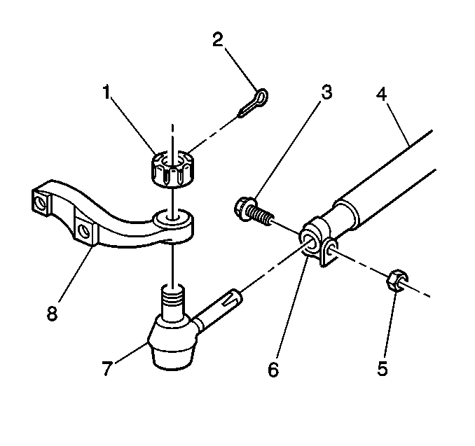
| • | The amount of threads visible on the tie rod. |
| • | The position of the tie rod end clamps (6). |
| • | The direction from which the clamp bolts are installed. |
| • | The tie rod adjuster tube (4) components may be rusted. Apply penetrating oil between the clamp and the tube. Rotate the clamps until the clamps move freely. |
| • | Ensure that these parts are reinstalled in the proper position. Correct reinstallation prevents interference with the adjacent parts of the vehicle. |

Tie Rod Installation Procedure
- Install the tie rod ball joint (7) in to the tie rod tube (4).
- Install the tie rod ball joint (7) into the tie rod arm (8).
- Install the new ball joint nut (1).
- Tighten the ball joint nut in the axle assembly.
- Advance the ball joint nut (1) to the nearest cotter pin slot.
- Install a new cotter pin (2).
- Lubricate the tie rod ball with chassis lubricant. Refer to Fluid and Lubricant Recommendations in the Maintenance and Lubrication sub-section of the appropriate Service Manual.
- Adjust the toe-in. Refer to Front Toe Adjustment in the Wheel Alignment sub-section of the appropriate Service Manual.
- Tighten the tie rod tube clamp bolt nuts (5).
- Install the GM Campaign Identification Label.

Important: Thread the tie rod assembly into the tie rod tube with the same amount of threads visible as noted prior to removal.
Notice: Use the correct fastener in the correct location. Replacement fasteners must be the correct part number for that application. Fasteners requiring replacement or fasteners requiring the use of thread locking compound or sealant are identified in the service procedure. Do not use paints, lubricants or corrosion inhibitors on fasteners or fastener joint surfaces unless specified. These coatings affect fastener torque and joint clamping force and may damage the fastener. Use the correct tightening sequence and specifications when installing fasteners in order to avoid damage to parts and systems.
Tighten
Tighten the nut to 129 N·m (95 lb ft).
Important: Do not back off a ball joint nut in order to insert a cotter pin.
Tighten
Tighten the nuts to 75 N·m (55 lb ft).
Campaign Identification Label
FOR US AND IPC
Place a Campaign Identification Label on each vehicle corrected in accordance with the instructions outlined in this Product Campaign Bulletin. Each label provides a space to include the campaign number and the five (5) digit dealer code of the dealer performing the campaign service. This information may be inserted with a typewriter or a ball point pen.
Put the Campaign Identification Label on a clean and dry surface of the radiator core support in an area that will be visible to people servicing the vehicle. When installing the Campaign Identification Label, be sure to pull the tab to allow the adhesion of the clear protective covering. Additional Campaign Identification Labels for US dealers can be obtained from Dealer Support Material by calling 1-888-549-6152 (Monday-Friday, 8:00 am to 5:00 pm EST). Ask for Item Number S-1015 when ordering.
Additional Campaign Identification Labels for IPC dealers can be obtained from your Regional Marketing Office.
Campaign Identification Label
FOR CANADA
Place a Campaign Identification Label on each vehicle corrected in accordance with the instructions outlined in this Product Campaign Bulletin. Each label provides a space to include the campaign number and the five (5) digit dealer code of the dealer performing the campaign service. This information may be inserted with a typewriter or a ball point pen.
Put the Campaign Identification Label on a clean and dry surface of the radiator core support in an area that will be visible to people servicing the vehicle. Additional Campaign Identification Labels for Canadian dealers can be obtained from DGN by calling 1-800-668-5539 (Monday-Friday, 8:00 am to 5:00 pm EST). Ask for Item Number GMP 91 when ordering.
Claim Information
Submit a Product Campaign Claim with the information indicated below:
Repair Performed | Part Count | Part No. | Parts Allow | CC-FC | Labor Op | Labor Hours* |
|---|---|---|---|---|---|---|
Inspect Tie Rod/Relay Rod Ends - No Further Action Required | 0 | NA | NA | MA-96 | V0702 | 0.2 |
Inspect & Replace Relay Rod Assembly | 3 | -- | ** | MA-96 | V0703 | 0.4 |
Add: Replace One Tie Rod End | 2 | 1.2 | ||||
Add: Replace Both Tie Rod Ends | 4 | 1.7 | ||||
Inspect & Replace One Tie Rod End (No Relay Rod Replacement) | 2 | -- | ** | MA-96 | V0704 | 1.3 |
Add: Replace 2nd Tie Rod End | 2 | 0.4 | ||||
* -- For Campaign Administrative Allowance, add 0.1 hours to the "Labor Hours". ** -- The "Parts Allowance" should be the sum total of the current GMSPO Dealer net price plus applicable Mark-Up or Landed Cost Mark-Up (for IPC) for parts needed to complete the repair. | ||||||
Refer to the General Motors WINS Claims Processing Manual for details on Product Campaign Claim Submission.
Customer Notification
FOR US AND CANADA
Customers will be notified of this campaign on their vehicles by General Motors (see copy of customer letter included with this bulletin).
Customer Notification
FOR IPC
Letters will be sent to known owners of record located within areas covered by the US National Traffic and Motor Vehicle Safety Act. For owners outside these areas, dealers should notify customers using the attached suggested dealer letter.
Dealer Campaign Responsibility
FOR US AND IPC (US States, Territories, and Possessions)
The US National Traffic and Motor Vehicle Safety Act provides that each vehicle which is subject to a recall campaign of this type must be adequately repaired within a reasonable time after the customer has tendered it for repair. A failure to repair within sixty days after tender of a vehicle is prima facie evidence of failure to repair within a reasonable time. If the condition is not adequately repaired within a reasonable time, the customer may be entitled to an identical or reasonably equivalent vehicle at no charge or to a refund of the purchase price less a reasonable allowance for depreciation. To avoid having to provide these burdensome remedies, every effort must be made to promptly schedule an appointment with each customer and to repair their vehicle as soon as possible. In the recall campaign notification letters, customers are told how to contact the US National Highway Traffic Safety Administration if the campaign is not completed within a reasonable time.
Dealer Campaign Responsibility
FOR ALL
All unsold new vehicles in dealers' possession and subject to this campaign MUST be held and inspected/repaired per the service procedure of this campaign bulletin BEFORE customers take possession of these vehicles.
Dealers are to service all vehicles subject to this campaign at no charge to customers, regardless of mileage, age of vehicle, or ownership, from this time forward.
Customers who have recently purchased vehicles sold from your vehicle inventory, and for which there is no customer information indicated on the dealer listing, are to be contacted by the dealer. Arrangements are to be made to make the required correction according to the instructions contained in this bulletin. This could be done by mailing to such customers a copy of the customer letter accompanying this bulletin. Campaign follow-up cards should not be used for this purpose, since the customer may not as yet have received the notification letter.
In summary, whenever a vehicle subject to this campaign enters your vehicle inventory, or is in your dealership for service in the future, please take the steps necessary to be sure the campaign correction has been made before selling or releasing the vehicle.
April, 2001Dear General Motors Customer:
This notice is sent to you in accordance with the requirements of the National Traffic and Motor Vehicle Safety Act.
Reason For This Recall
General Motors has decided that a defect which relates to motor vehicle safety exists in certain 1999 and 2000 Chevrolet and GMC C-Series, T-Series and B-Series vehicles. Some of these vehicles have a condition in which the bearing ball sockets in the tie rods and/or the relay rod may not have been manufactured to the print specification for case depth and hardness, resulting in the potential for premature wear-out and eventual joint separation. These tie rod ends and relay rods were used in the production of new vehicles and as service parts for vehicle repairs. As the joint wears, the driver may notice a loose, on-center steering feel. If the vehicle continued to be operated in this condition, a tie rod or relay rod joint could separate from the socket. If a tie rod were to separate, vehicle control could still be maintained; however, there would be noticeable steering vagueness, and the vehicle would have a tendency to wander. If a relay rod socket were to separate, steering control would be lost and a vehicle crash could occur without prior warning.
What Will Be Done
Your dealer will inspect both tie rod ends and/or the relay rod on your vehicle and replace any that have the suspect socket date code. This service will be performed for you at no charge .
How Long Will The Repair Take?
The length of time required to perform this inspection is approximately 15 minutes. Another fifteen minutes to one hour and thirty minutes may be necessary if part replacement is required. Additional time may be required to schedule and process your vehicle. If you dealer has a large number of vehicles awaiting service, this additional time may be significant. Please ask your dealer if you wish to know how much additional time will be needed to schedule, process and repair your vehicle.
Contacting Your Dealer
Please contact your dealer as soon as possible to arrange a service date. Parts are available and instructions for making this correction have been sent to your dealer.
Your dealer is best equipped to obtain parts and provide services to correct your vehicle as promptly as possible. Should your dealer be unable to schedule a service date within a reasonable time, you should contact the appropriate Customer Assistance Center at the number listed below:
Division | Number |
|---|---|
Chevrolet/GMC | 1-800-862-4389 |
GMODC | (905)644-4112 |
Puerto Rico - English | 1-800-496-9992 |
Puerto Rico - Español | 1-800-496-9993 |
Virgin Islands | 1-800-496-9994 |
If, after contacting the appropriate customer assistance center, you are still not satisfied that we have done our best to remedy this condition without charge and within a reasonable time, you may wish to write the Administrator, National Highway Traffic Safety Administration, 400 Seventh Street SW, Washington, DC 20590 or call 1-888-327-4236.
Customer Reply Card
The attached customer reply card identifies your vehicle. Presentation of this card to your dealer will assist in making the necessary correction in the shortest possible time. If you no longer own this vehicle, please let us know by completing the attached and mailing it in the postage paid envelope.
We are sorry to cause you this inconvenience; however, we have taken this action in the interest of your safety and continued satisfaction with our products.
General Motors Corporation
Enclosure
