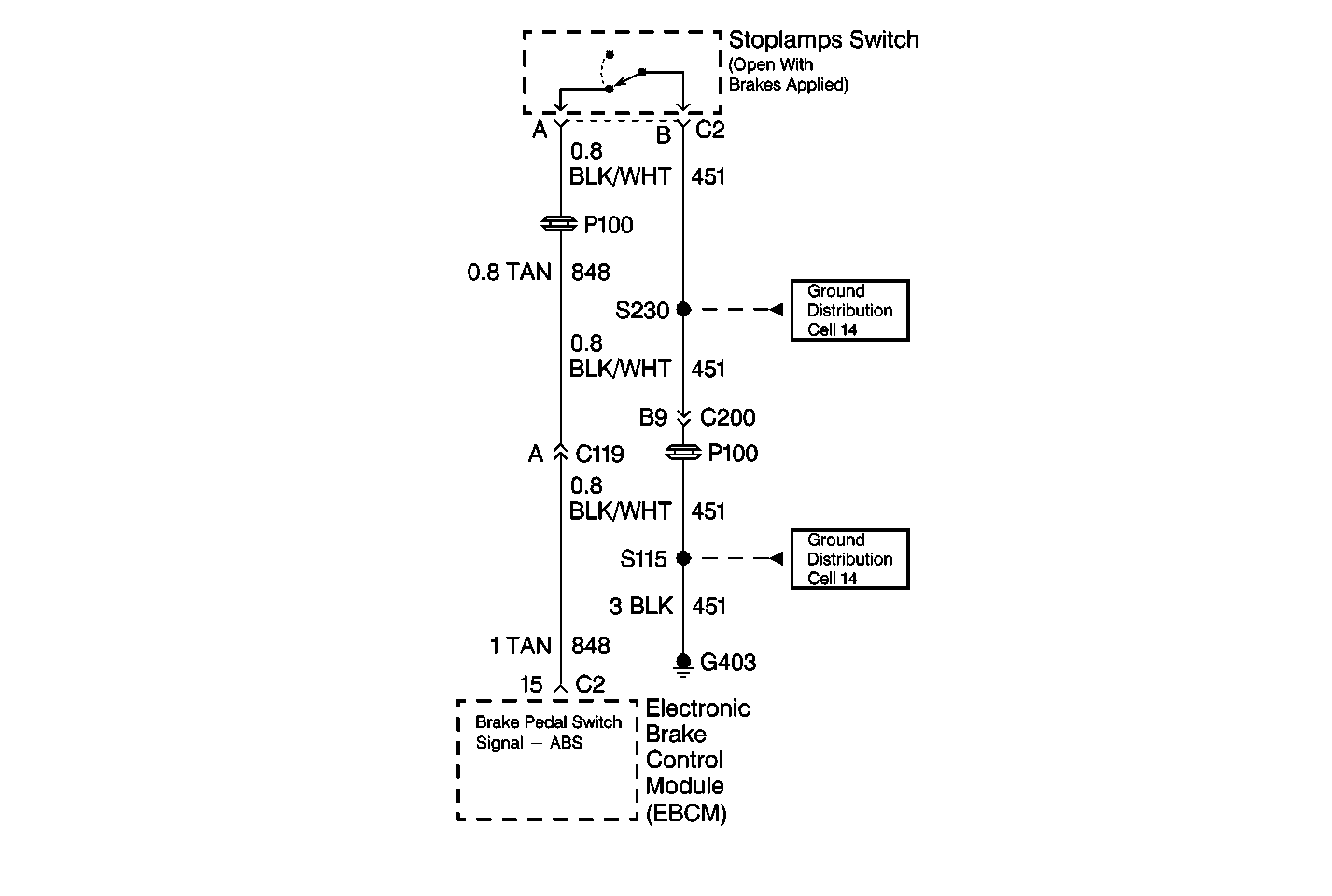
Circuit Description
The Stoplamp Switch is normally closed. With the ignition in the RUN position and the brake pedal not depressed, the EBCM will have ignition voltage present at terminal 15 of the 24-way connector. When the brakes are applied, the voltage present at terminal 15 of the EBCM will be zero.
Conditions for Setting the DTC
| • | Vehicle above 56 km/h (35 mph) for 10 seconds, followed by vehicle at rest for 1 second. |
| • | Stoplamp never switching during the above condition |
Action Taken When the DTC Sets
| • | The ABS indicator lamp will not be illuminated. |
| • | The ABS will not be disabled. |
DTC C0281 is advisory code only. The DTC is stored in memory, but the ABS indicator lamp will not light, and ABS will not be disabled.
Conditions for Clearing the DTC
| • | Repair the conditions responsible for setting the DTC. |
| • | Use the Scan Tool Clear DTCs function. |
Diagnostic Aids
DTC C0281 can be set by a faulty Stoplamp Switch, misadjusted Stoplamp Switch or damage in CKT 848 or CKT 451. Also, a driver who rides the brake at power-up through 24 km/h (15 mph) can set this DTC.
Thoroughly check any circuitry that is suspected of causing the intermittent complaint for the following conditions:
| • | Backed out terminals |
| • | Improper mating |
| • | Broken locks |
| • | Improperly formed or damaged terminals |
| • | Poor terminal to wiring connections |
| • | Physical damage to the wiring harness |
Test Description
The numbers below refer to the steps in the diagnostic table:
-
This step checks the functionality of the Stoplamp Switch circuit using the Scan Tool .
-
This step checks the functionality of the Stoplamp Switch circuit (including the Inverter Driving Module) using a J 39200 .
-
This step checks the functionality of the Stoplamp Switch circuit up to the Inverting Driving Module.
-
This step checks for a short to ground in the Stoplamp Switch circuit between the Inverting Driver Module and the EBCM.
-
This step checks the resistance in the ground circuit to the Inverting Driver Module.
-
This step checks the ignition voltage at the Inverting Driver Module.
Step | Action | Value(s) | Yes | No |
|---|---|---|---|---|
1 | Was the Diagnostic System Check performed? | -- | Go to Step 2 | Go to Diagnostic System Check |
Does the scan tool indicate that the Stoplamp Switch is opening and closing? | -- | Go to Step 8 | Go to Step 3 | |
Is the resistance measured switching between the specified range? | 0-2 ohms Pedal released OL Pedal applied | Go to Step 8 | Go to Step 4 | |
Is the resistance within the specified range? | 0-2 ohms | Go to Step 5 | Go to Step 10 | |
5 | Using a J 39200 , measure the resistance between terminal B of the Stoplamp Switch harness connector and ground. Is the resistance within the specified range? | 0-2 ohms | Go to Step 6 | Go to Step 9 |
6 | Check for a properly adjusted Stoplamp Switch. Is the Stoplamp Switch adjustment correct? | -- | Go to Step 7 | Go to Step 11 |
7 | Using a J 39200 , measure the resistance between terminal A and terminal B of the Stop Lamp Switch while applying and releasing the brake pedal. Is the resistance measured switching between the specified range? | 0-2ohms Pedal released OL Pedal applied | Go to Diagnostic Aids | Go to Step 12 |
Does DTC C0281 set as a current DTC? | -- | Go to Step 13 | Go to Diagnostic Aids | |
Repair the open or high resistance in CKT 451. Refer to Wiring Repairs in Wiring Systems. Is the repair complete? | -- | Go to Diagnostic System Check | -- | |
Repair the open or high resistance in CKT 848. Refer to Wiring Repairs in Wiring Systems. Is the repair complete? | -- | Go to Diagnostic System Check | -- | |
11 | Repair the misadjusted Stoplamp Switch. Is the repair complete? | -- | Go to Diagnostic System Check | -- |
12 | Replace the Stoplamp Switch. Refer to
Is the repair complete? | -- | Go to Diagnostic System Check | -- |
13 | Replace the EBCM. Refer to Electronic Brake Control Module Replacement . Is the repair complete? | -- | Go to Diagnostic System Check | -- |

