Tools Required
Notice: Any new rotor must have the protective coating removed from the friction surfaces before being placed in service. Remove the protective coating using
denatured alcohol or an equivalent brake cleaner, and wipe the surface clean with clean cloths. Do not use gasoline, kerosene, or other oil base solvents which may leave an oily residue. This residue is damaging to the brake lining and is flammable.
Removal Procedure
You can remove the brake rotor without separating the caliper from the mounting bracket.
- Release the parking brake.
- Remove 2/3 of the brake fluid from the master cylinder.
- Raise and support the vehicle. Refer to
Lifting and Jacking the Vehicle
in General Information.
- Remove the tire and wheel assembly. Refer to
Tire and Wheel Removal and Installation
- Remove the caliper and mounting bracket as an assembly. Refer to
Rear Disc Brake Pads Replacement
.
- Hang the caliper and mounting bracket assembly from the suspension using mechanics wire.

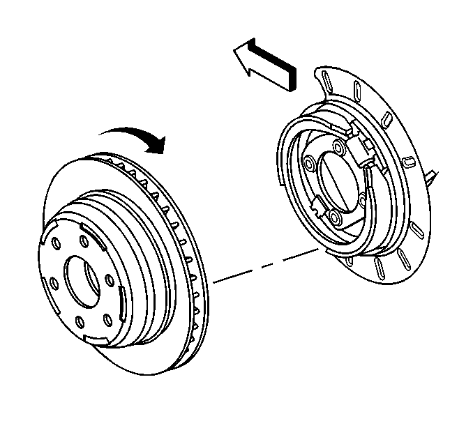
- Remove the rotor. Slowly turn the rotor while pulling the rotor away from the axle. (15 series).

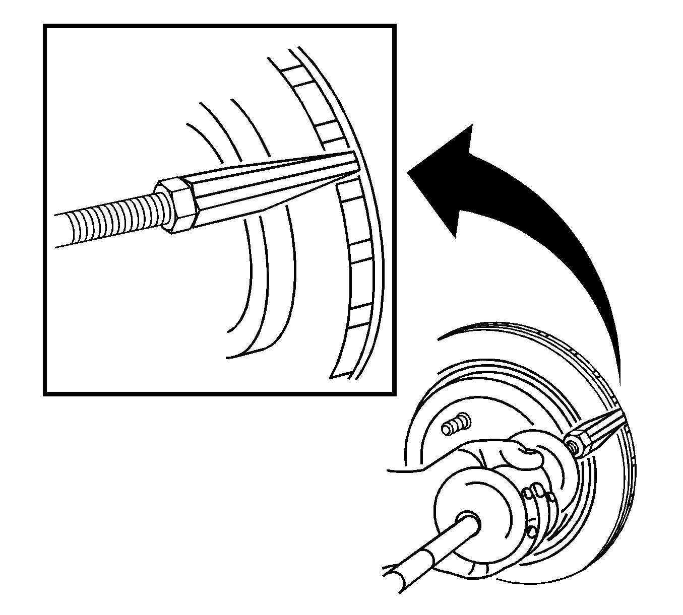
- If the brake rotor cannot be removed perform the following:
| 8.2. | Insert
J-46277
between the rotor friction surfaces in the vent section of the rotor. |
DO NOT place the
J-46277
on the rotor friction
surface.
| 8.4. | Inspect the park brake components for the following conditions: |
| • | Bent or broken hold down spring |
| • | Broken, cracked or worn brake shoe lining |
| • | Bent or damaged brake shoe |
| • | Worn, bent or damaged backing plate |
| 8.5. | If any of these conditions are found replace the affected parts. |

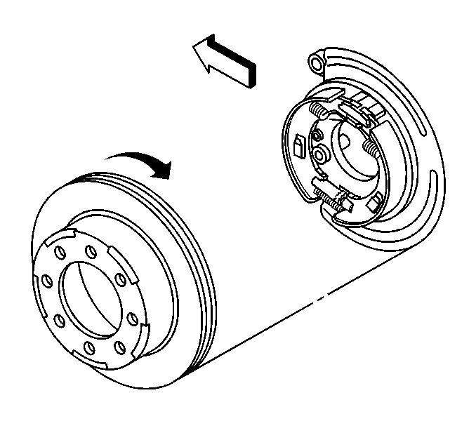
- Remove the rotor. Slowly turn the rotor while pulling the rotor away from the axle. (25 series).
Installation Procedure
Important: Whenever the brake rotor has been separated from the hub/axle flange, any rust or contaminants should be cleaned from the hub/axle flange and the brake rotor mating surfaces. Failure to do this may result in excessive
assembled lateral runout (LRO) of the brake rotor, which could lead to brake pulsation.
- Using the
J 42450-A
, thoroughly clean any rust or corrosion from the mating surface of the hub/axle flange.
- Using the
J 41013
, thoroughly clean any rust or corrosion from the mating surface and mounting surface of the brake rotor.
- Inspect the mating surfaces of the hub/axle flange and the rotor to ensure that there are no foreign particles or debris remaining.

- Install the rotor. Slowly turn the rotor while pushing the rotor towards the axle. (15 series).

- Install the rotor. Slowly turn the rotor while pushing the rotor towards the axle. (25 series).
- Install the caliper and the mounting bracket as an assembly. Refer to
Rear Disc Brake Pads Replacement
.
- Install the tire and wheel assembly. Refer to
Tire and Wheel Removal and Installation
.
- Remove the safety stands.
- Lower the vehicle.


