Ignition and Key Alarm Switch Assembly - Disassemble - Off Vehicle Floor Shift
Tools Required
J-42759 Ignition Switch Connector Release Tool
- Disable the inflatable restraint steering wheel module. Refer to Disabling the SIR System .
- Remove the upper and lower trim covers. Refer to Steering Column Trim Covers - Disassemble - Off Vehicle .
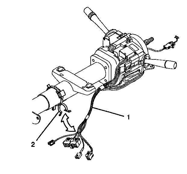
- Remove the wire harness assembly (1) from the wire restraint clip (2).
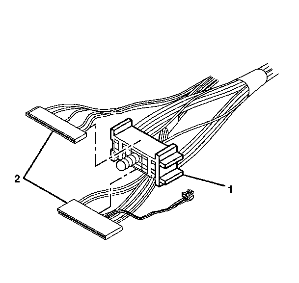
- Slide the 2 connectors (2) of the turn signal and multifunction switch assembly out of the bulkhead connector (1).
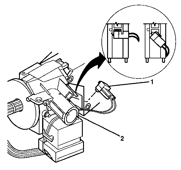
- Remove the key alarm connector (1) from the electronic lock module assembly (2) in the following way:
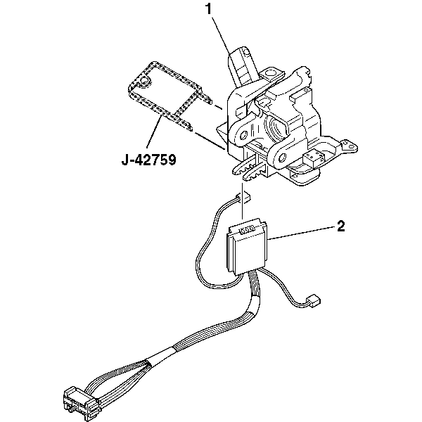
- Insert J-42759 into the electronic lock module assembly (1) and slide the ignition and key alarm switch assembly (2) out.

Caution: This vehicle is equipped with a Supplemental Inflatable Restraint (SIR) System. Failure to follow the correct procedure could cause the following conditions:
• Air bag deployment • Personal injury • Unnecessary SIR system repairs • Refer to SIR Component Views in order to determine if you are performing service on or near the SIR components or the SIR wiring. • If you are performing service on or near the SIR components or the SIR wiring, disable the SIR system. Refer to Disabling the SIR System.
Important: The abrasion sleeve located on the steering column wire harness assembly must be reinstalled. Make note of what connector (electronic lock module assembly) is coming out of the middle of the abrasion sleeve for installation purposes.


| 5.1. | Rotate the key alarm connector (1) 90 degrees. |
| 5.2. | Pull the key alarm connector (1) out of the electronic lock module assembly (2). |
| 5.3. | Remove the passkey connector from the electronic lock module assembly (2). |

Ignition and Key Alarm Switch Assembly - Disassemble - Off Vehicle Column Shift
Tools Required
J-42759 Ignition Switch Connector Release Tool
- Disable the inflatable restraint steering wheel module. Refer to Disabling the SIR System .
- Remove the upper and lower trim covers. Refer to Steering Column Trim Covers - Disassemble - Off Vehicle .
- Remove the wire harness strap (2) from the steering column and the wire harness assembly (1).
- Slide the 2 connectors (2) of the turn signal and multifunction switch assembly out of the bulkhead connector (1).
- Rotate the key alarm connector (1) 90 degrees.
- Pull the key alarm connector (1) out of the electronic lock module assembly (2).
- Remove the passkey connector from the electronic lock module assembly (2).
- Insert J-42759 into the electronic lock module assembly (1) and slide the ignition and key alarm switch assembly (2) out.

Caution: This vehicle is equipped with a Supplemental Inflatable Restraint (SIR) System. Failure to follow the correct procedure could cause the following conditions:
• Air bag deployment • Personal injury • Unnecessary SIR system repairs • Refer to SIR Component Views in order to determine if you are performing service on or near the SIR components or the SIR wiring. • If you are performing service on or near the SIR components or the SIR wiring, disable the SIR system. Refer to Disabling the SIR System.
Important: The abrasion sleeve located on the steering column wire harness assembly must be reinstalled. Make note of what connector (electronic lock module assembly) is coming out of the middle of the abrasion sleeve for installation purposes.


Ignition and Key Alarm Switch Assembly - Disassemble - Off Vehicle Export
Tools Required
J-42759 Ignition Switch Connector Release Tool
- Remove the upper and lower trim covers. Refer to Steering Column Trim Covers - Disassemble - Off Vehicle .
- Remove the wire harness strap (2) from the steering column and the wire harness assembly (1).
- Slide the 2 connectors (2) of the turn signal and multifunction switch assembly out of the bulkhead connector (1).
- Rotate the key alarm connector (1) 90 degrees.
- Pull the key alarm connector (1) out of the electronic lock module assembly (2).
- Remove the passkey connector from the electronic lock module assembly (2).
- Slide the ignition and key alarm switch assembly (2) out of the electronic lock module assembly (1) using J-42759 .


