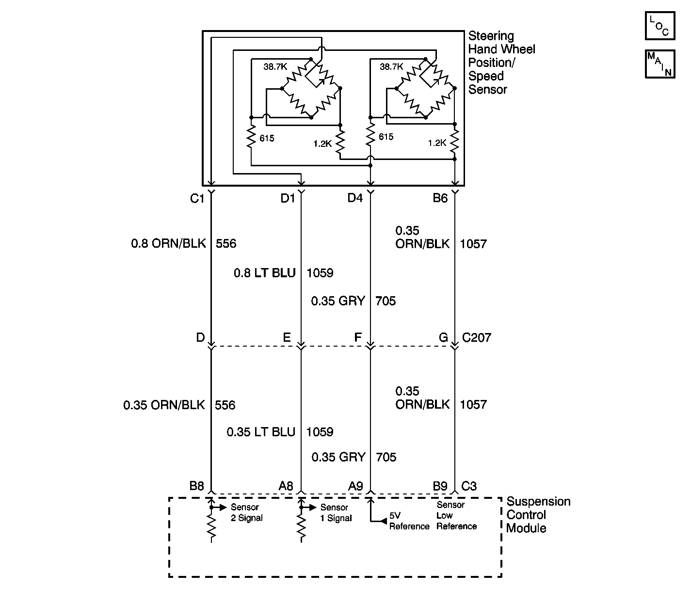
Circuit Description
The steering handwheel position/speed sensor is a 0 to 5 volt device which is used to measure steering wheel position. This information is then used by the control module to estimate vehicle lateral acceleration. The two valid output signals are in the 0.35 to 4.75 volt range. These output voltages will increase or decrease within the valid voltage range as the steering wheel is rotated. The sensor is mounted at the base of the steering column.
Conditions for Running the DTC
Vehicle speed is greater than 50 MPH for at least 10 seconds.
Conditions for Setting the DTC
The suspension control module detects a steering handwheel position/speed sensor out-of-range condition when the vehicle speed is greater than 50 MPH for at least 10 seconds.
Action Taken When the DTC Sets
The electronic variable orifice (EVO) outputs will be disabled.
Conditions for Clearing the MIL/DTC
| • | The suspension control module no longer detects a steering handwheel position/speed sensor out-of-range condition. |
| • | A history DTC will clear after 100 consecutive ignition cycles if the condition for the malfunction is no longer present. |
| • | Using the scan tool. |
Diagnostic Aids
The following conditions may cause a malfunction to occur:
| • | There is a short to ground or voltage on the sensor 1 signal circuit. |
| • | There is a open in the sensor 1 signal circuit. |
| • | There is a loose or poorly seated connector. |
Test Description
The number(s) below refer to the step number(s) on the diagnostic table.
-
Checking sensor voltage range.
-
Tests for the proper operation of the circuit in the high voltage range.
-
Tests for the proper operation of the circuit in the low voltage range. If the fuse in the jumper opens when you perform this test, the sensor 1 signal circuit is shorted to voltage.
-
Tests for a short to ground in the 5 volt reference circuit.
-
Test for a short to voltage, a high resistance, or an open circuit.
-
The control module must be re-calibrated.
Step | Action | Value(s) | Yes | No |
|---|---|---|---|---|
1 | Did you perform the RTD Diagnostic System Check? | -- | Go to Step 2 | Go to Diagnostic System Check |
Does the scan tool indicate that the steering handwheel position/speed sensor 1 data parameter changes within the specified range? | 0.35 -4.7 volts | Go to Diagnostic Aids | Go to Step 3 | |
Does the scan tool indicate that the steering handwheel position/speed sensor 1 data parameter is greater than the specified value? | 4.7 volts | Go to Step 4 | Go to Step 8 | |
Does the scan tool indicate that the steering handwheel position/speed sensor data parameter is less than the specified value? | 0.35 volts | Go to Step 5 | Go to Step 9 | |
Test the 5 volt reference circuit of the steering handwheel position/speed sensor for a short to ground. Refer to Circuit Testing and Wiring Repairs in Wiring Systems. Did you find and correct the condition? | -- | Go to Step 7 | Go to Step 6 | |
6 |
Does the scan tool indicate that the steering position sensor 1 data parameter is greater than the specified value? | 4.7 volts | Go to Step 15 | Go to Step 12 |
Test the 5 volt reference circuit of the steering handwheel position/speed sensor for a short to voltage, a high resistance, or an open. Refer to Circuit Testing and Wiring Repairs in Wiring Systems. Did you find and correct the condition? | -- | Go to Step 15 | Go to Step 11 | |
8 | Test the sensor 1 signal circuit of the steering handwheel position/speed sensor for a short to ground. Refer to Circuit Testing and Wiring Repairs in Wiring Systems. Did you find and correct the condition? | -- | Go to Step 15 | Go to Step 12 |
9 | Test the sensor 1 signal circuit of the steering handwheel position/speed sensor for a short to voltage, a high resistance, and an open circuit. Refer to Circuit Testing and Wiring Repairs in Wiring Systems. Did you find and correct the condition? | -- | Go to Step 15 | Go to Step 10 |
10 | Test the sensor low reference circuit of the steering handwheel position/speed sensor for high resistance and an open circuit. Refer to Circuit Testing and Wiring Repairs in Wiring Systems. Did you find and correct the condition? | -- | Go to Step 15 | Go to Step 12 |
11 | Inspect for poor connections at the harness connector of the steering handwheel position/speed sensor. Refer to Testing for Intermittent Conditions and Poor Connections and Connector Repairs in Wiring Systems. Did you find and correct the condition? | -- | Go to Step 15 | Go to Step 13 |
12 | Inspect for poor connections at the harness connector of the suspension control module. Refer to Testing for Intermittent Conditions and Poor Connections and Connector Repairs in Wiring Systems. Did you find and correct the condition? | -- | Go to Step 15 | Go to Step 14 |
13 | Replace the steering handwheel position/speed sensor. Refer to Steering Wheel Position Sensor or Steering Shaft Lower Bearing Replacement . Did you complete the replacement? | -- | Go to Step 15 | -- |
|
Important: Perform the set up procedure for the suspension control module when replacement is necessary. Replace the suspension control module. Refer to Electronic Suspension Control Module Replacement . Did you complete the replacement? | -- | Go to Step 15 | -- | |
15 |
Does the DTC reset? | -- | Go to Step 2 | System OK |
