Engine Coolant Thermostat Replacement 4.3 L Engine
Removal Procedure
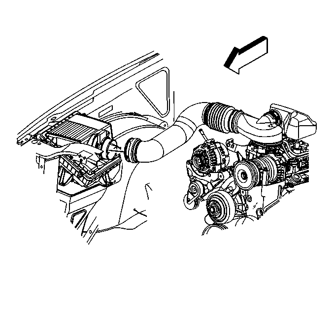
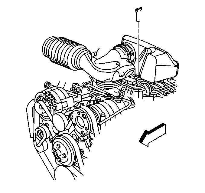
- Separate the MAF/IAT sensor assembly and the air inlet tube by loosening the hose clamp.
- Disconnect the PCV hose from the air cleaner outlet duct.
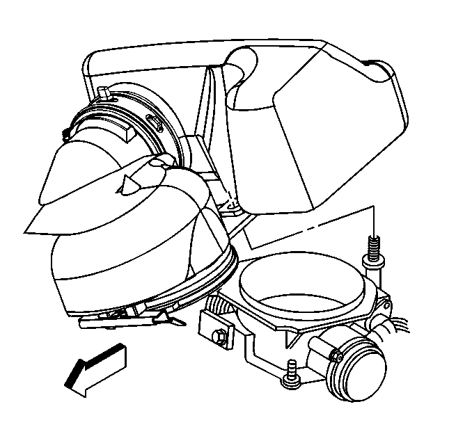
- Remove the air inlet tube and resonator retaining wing nut.
- Remove the air inlet tube and resonator from the throttle body by pivoting the air inlet tube and resonator upward until the hinge clip releases from the lip on the throttle body.
- Drain the cooling system. Refer to Cooling System Draining and Filling .
- Remove the radiator inlet hose. Refer to Radiator Inlet Hose Replacement .
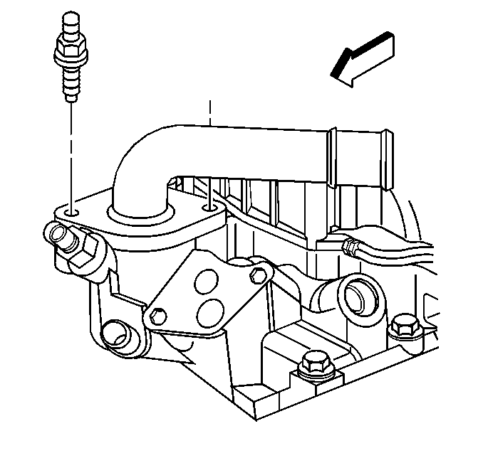
- Remove the coolant outlet studs.
- Remove the coolant outlet from the lower intake manifold.
- Remove the thermostat.
- Clean all the sealing surfaces of the coolant outlet.
- Clean the sealing surface on the lower intake manifold.
- Remove the O-ring seal from the thermostat and discard.
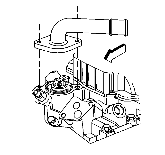
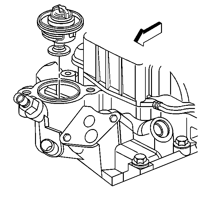
Installation Procedure
Important: In order to prevent leakage, thoroughly clean all the parts and the sealing surfaces.
- Install the new O-ring seal to the thermostat.
- Install the thermostat into the lower intake manifold.
- Install a new gasket .
- Install the coolant outlet on the lower intake manifold.
- Install the coolant outlet studs.
- Install the radiator inlet hose. Refer to Radiator Inlet Hose Replacement .
- Align the hinge clip with the lip on the throttle body.
- Install the resonator retaining wing nut.
- Connect the PCV hose to the air cleaner outlet duct.
- Connect the MAF/IAT sensor assembly harness connector.
- Fill the cooling system. Refer to Cooling System Draining and Filling .
- Inspect the cooling system for leaks.


Notice: Use the correct fastener in the correct location. Replacement fasteners must be the correct part number for that application. Fasteners requiring replacement or fasteners requiring the use of thread locking compound or sealant are identified in the service procedure. Do not use paints, lubricants, or corrosion inhibitors on fasteners or fastener joint surfaces unless specified. These coatings affect fastener torque and joint clamping force and may damage the fastener. Use the correct tightening sequence and specifications when installing fasteners in order to avoid damage to parts and systems.
Tighten
Tighten the coolant outlet studs to 19 N·m (14 lb ft).

Install the air inlet tube and resonator to the throttle body by pivoting the air inlet tube and resonator downward until the mounting stud is through the hole in the air inlet tube.

Tighten
Tighten the resonator wing nut to 3 N·m (27 lb in).
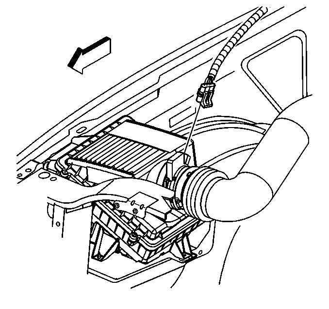
Engine Coolant Thermostat Replacement 4.8 L, 5.3 L, and 6.0 L Engines
Removal Procedure
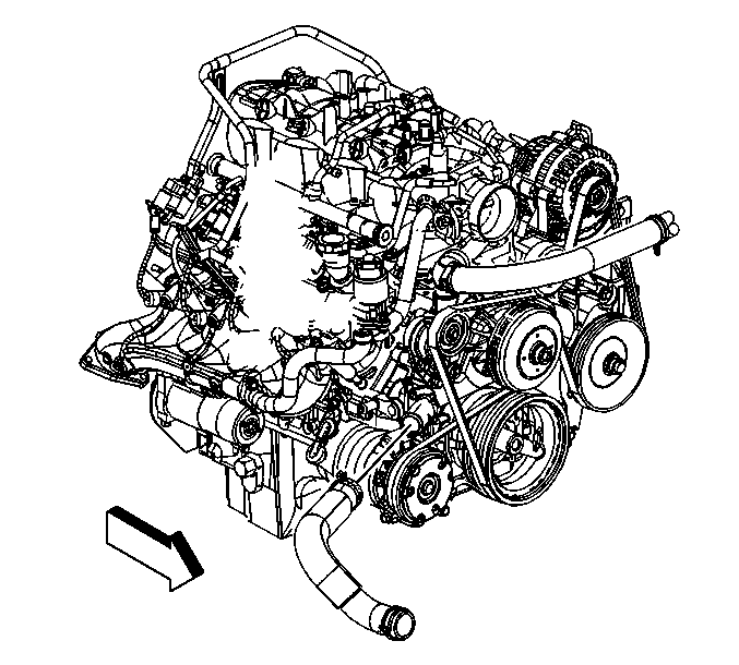
Important: The thermostat is not serviceable separately. The water pump inlet and thermostat must be replaced as an assembly.
- Drain the cooling system. Refer to Cooling System Draining and Filling .
- Loosen the air cleaner outlet duct clamps at the following locations:
- Remove the radiator inlet hose clip from the outlet duct.
- Remove the air cleaner outlet duct.
- Reposition the outlet hose clamp at the water pump.
- Remove the outlet hose from the water pump.
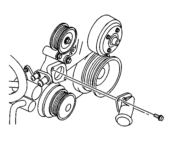
- Remove the water pump inlet bolts.
- Remove the water pump inlet and thermostat from the water pump.
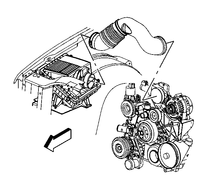
| • | Throttle body |
| • | Mass airflow/intake air temperature (MAF/IAT) sensor |
Installation Procedure
- Install the thermostat and water pump inlet to the water pump.
- Install the water pump inlet bolts.
- Install the outlet hose to the water pump.
- Position the outlet hose clamp at the water pump.
- Install the air cleaner outlet duct.
- Install the radiator inlet hose clip to the outlet duct.
- Tighten the air cleaner outlet duct clamps at the following locations:
- Fill the cooling system. Refer to Cooling System Draining and Filling .

Notice: Use the correct fastener in the correct location. Replacement fasteners must be the correct part number for that application. Fasteners requiring replacement or fasteners requiring the use of thread locking compound or sealant are identified in the service procedure. Do not use paints, lubricants, or corrosion inhibitors on fasteners or fastener joint surfaces unless specified. These coatings affect fastener torque and joint clamping force and may damage the fastener. Use the correct tightening sequence and specifications when installing fasteners in order to avoid damage to parts and systems.
Tighten
Tighten the water pump inlet bolts to 15 N·m (11 lb ft).


Important: Align the arrow at the throttle body end of the duct with the throttle body attaching stud.
| • | Throttle body |
| • | MAF/IAT sensor |
Tighten
Tighten the air cleaner outlet duct clamp screws to 7 N·m
(62 lb in).
Engine Coolant Thermostat Replacement 8.1 L Engine
Removal Procedure
- Drain the cooling system. Refer to Cooling System Draining and Filling .
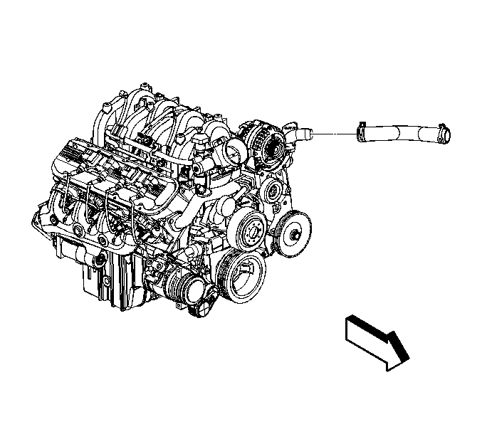
- Reposition the inlet hose clamp at the water outlet.
- Remove the inlet hose from the water outlet.
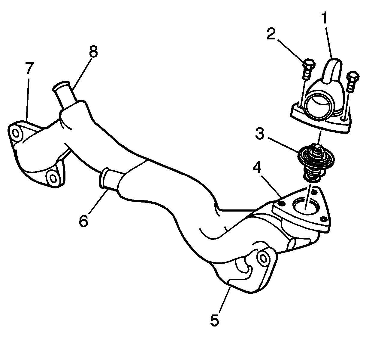
- Remove the water outlet bolts (2).
- Remove the water outlet (1).
- Remove the thermostat (3).
Installation Procedure
- Install the thermostat (3).
- Install the water outlet (1).
- Install the water outlet bolts.
- Install the inlet hose to the water outlet.
- Position the inlet hose clamp at the water outlet.
- Fill the cooling system. Refer to Cooling System Draining and Filling .

Notice: Use the correct fastener in the correct location. Replacement fasteners must be the correct part number for that application. Fasteners requiring replacement or fasteners requiring the use of thread locking compound or sealant are identified in the service procedure. Do not use paints, lubricants, or corrosion inhibitors on fasteners or fastener joint surfaces unless specified. These coatings affect fastener torque and joint clamping force and may damage the fastener. Use the correct tightening sequence and specifications when installing fasteners in order to avoid damage to parts and systems.
Tighten
Tighten the water outlet bolts to 30 N·m (22 lb ft).

Engine Coolant Thermostat Replacement 6.6 L Engine
Removal Procedure
- Drain the engine coolant. Refer to Cooling System Draining and Filling .
- Remove the water outlet tube. Refer to Water Outlet Tube Replacement .
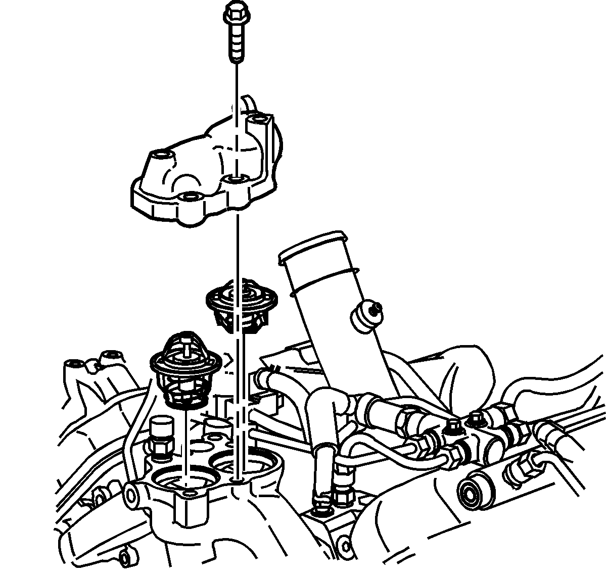
- Remove the bolt for the fuel line bracket.
- Remove the 4 bolts retaining the thermostat housing cover.
- Remove the 2 thermostats with the seals.
Inspection and Repair Procedure
- Inspect the thermostats for sticking, cracks, and leakage of wax.
- Replace the thermostats if damage is found.
- Clean the thermostat housing and thermostat housing cover sealing surfaces.
Installation Procedure
- Install the 2 thermostats with the seals to the thermostat housing.
- Install the thermostat housing cover.
- Install the fuel line bracket bolt.
- Install the water outlet tube. Refer to Water Outlet Tube Replacement .
- Fill the engine coolant. Refer to Cooling System Draining and Filling .
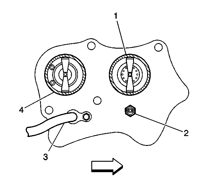
The rear thermostat (4) has 2 vent valves. Install with the vent valves towards the rear of engine.

Notice: Use the correct fastener in the correct location. Replacement fasteners must be the correct part number for that application. Fasteners requiring replacement or fasteners requiring the use of thread locking compound or sealant are identified in the service procedure. Do not use paints, lubricants, or corrosion inhibitors on fasteners or fastener joint surfaces unless specified. These coatings affect fastener torque and joint clamping force and may damage the fastener. Use the correct tightening sequence and specifications when installing fasteners in order to avoid damage to parts and systems.
Tighten
Tighten the thermostat housing cover bolts to 21 N·m (15 lb ft).
Tighten
Tighten the fuel line bracket and bolt to 21 N·m (1 lb ft).
