GM Service Manual Online
For 1990-2009 cars only

Removal Procedure


    Object Number: 360851  Size: SH
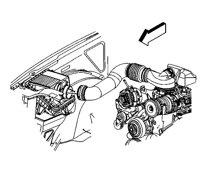
  1. Separate the MAF/IAT sensor assembly and the air inlet tube by loosening the hose clamp.
  2. Disconnect the PCV hose from the air cleaner outlet duct.

  3. Object Number: 489179  Size: SH
  4. Remove the air inlet tube and resonator retaining wing nut.

  5. Object Number: 489176  Size: SH
  6. Remove the air inlet tube and resonator from the throttle body by pivoting the air inlet tube and resonator upward until the hinge clip releases from the lip on the throttle body.

  7. Object Number: 398868  Size: SH
  8. Disconnect the secondary air injection (AIR) pipe assembly from the AIR crossover pipe and the AIR pump, if equipped.
  9. Remove the AIR pipe assembly from the exhaust manifold, if equipped. Refer to Secondary Air Injection Check Valve and Check Valve Pipe Replacement - Bank 2 in Engine Controls - 4.3L.

  10. Object Number: 316440  Size: SH
  11. Remove the heater hose bracket bolt.
  12. Move and secure the heater hoses out of the way.
  13. Move and secure the engine wiring harness out of the way.

  14. Object Number: 328568  Size: SH
  15. Remove the valve rocker arm cover bolts.
  16. Remove the valve rocker arm cover bolt grommets.
  17. Discard the valve rocker arm cover bolt grommets.

  18. Object Number: 480524  Size: SH
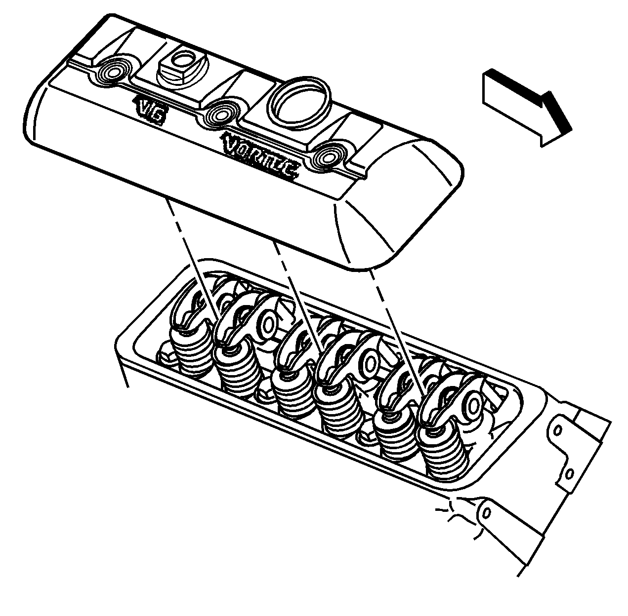
  19. Remove the valve rocker arm cover.

  20. Object Number: 328573  Size: SH
  21. Remove the valve rocker arm cover gasket.
  22. Discard the valve rocker arm cover gasket.

  23. Object Number: 334508  Size: SH

    Caution: Wear safety glasses in order to avoid eye damage.

  24. Clean the valve rocker arm cover in cleaning solvent.
  25. Dry the valve rocker arm cover with compressed air.
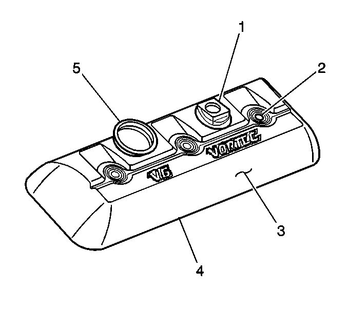
  26. Inspect the valve rocker arm cover for the following:
  27. • Damage to the PCV valve grommet (1)
    • Damage to the bolt holes (2)
    • A damaged valve rocker arm cover may interfere with the valve rocker arms.
    • Damage to the exterior of the valve rocker arm cover (3)
    • Gouges or damage to the sealing surface (4)
    • Damage to the oil fill tube grommet (5)
    • Restrictions to the ventilation system passages

Installation Procedure


    Object Number: 328573  Size: SH

    Important: Do not reuse the valve cover gasket or the valve rocker arm cover bolt grommets.

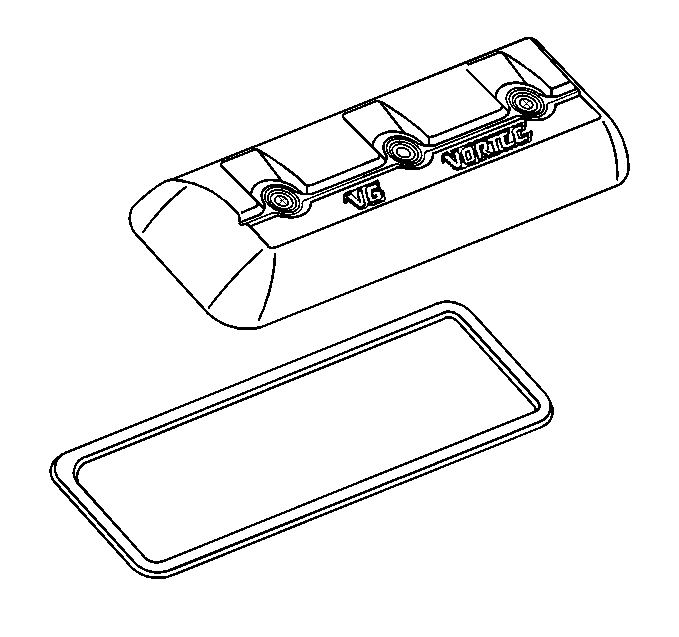
  1. Install the NEW valve rocker arm cover gasket into the groove of the valve rocker arm cover.
  2. Install the NEW valve rocker arm cover bolt grommets into the valve rocker arm cover.
  3. Object Number: 480524  Size: SH
  4. Install the valve rocker arm cover onto the cylinder head.
  5. Object Number: 328568  Size: SH

    Notice: Use the correct fastener in the correct location. Replacement fasteners must be the correct part number for that application. Fasteners requiring replacement or fasteners requiring the use of thread locking compound or sealant are identified in the service procedure. Do not use paints, lubricants, or corrosion inhibitors on fasteners or fastener joint surfaces unless specified. These coatings affect fastener torque and joint clamping force and may damage the fastener. Use the correct tightening sequence and specifications when installing fasteners in order to avoid damage to parts and systems.

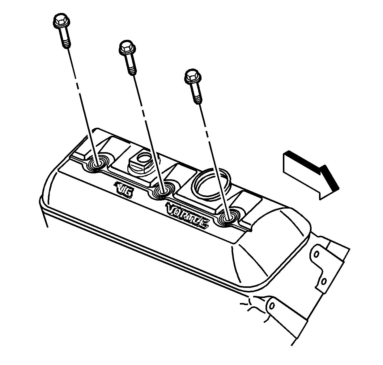
  6. Install the valve rocker arm cover bolts.
  7. Tighten
    Tighten the valve rocker arm cover bolts to 12 N·m (106 lb in).

    Object Number: 316440  Size: SH
  8. Reposition the engine wiring harness.
  9. Reposition the heater hoses.
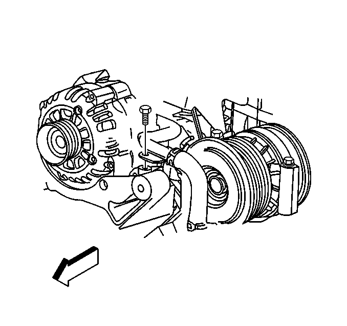
  10. Install the heater hose bracket bolt.
  11. Tighten
    Tighten the bracket bolt to 25 N·m (18 lb ft).

    Object Number: 398868  Size: SH
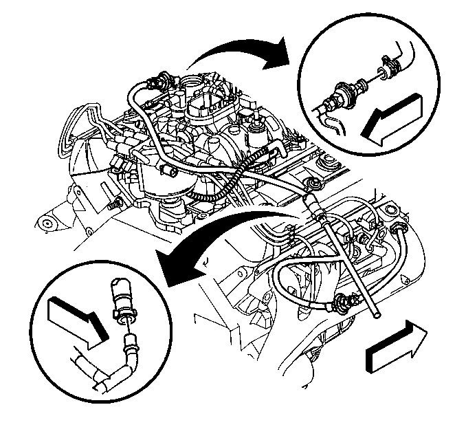
  12. Install the AIR pipe assembly to the exhaust manifold. Refer to Secondary Air Injection Check Valve and Check Valve Pipe Replacement - Bank 2 in Engine Controls - 4.3L.
  13. Connect the AIR pipe assembly to the AIR pump and the AIR crossover pipe.
  14. Object Number: 489176  Size: SH
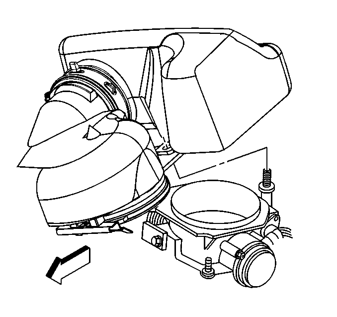
  15. Align the hinge clip with the lip on the throttle body.
  16. Install the air inlet tube and resonator to the throttle body by pivoting the air inlet tube and resonator downward until the mounting stud is through the hole in the air inlet tube.
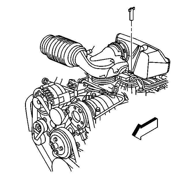

    Object Number: 489179  Size: SH
  17. Install the resonator retaining wing nut.
  18. Connect the PCV hose to the air cleaner outlet duct.
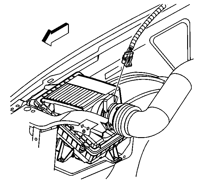
  19. Object Number: 373468  Size: SH
  20. Connect the MAF/IAT sensor assembly harness connector.