Removal Procedure
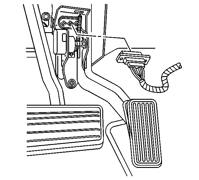
- Disconnect the APP sensor harness connector.
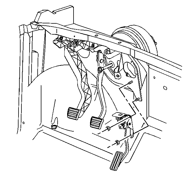
- Remove the accelerator pedal mounting nuts.
- Remove the APP assembly.

Notice: Handle the electronic throttle control components carefully. Use cleanliness in order to prevent damage. Do not drop the electronic throttle control components. Do not roughly handle the electronic throttle control components. Do not immerse the electronic throttle control components in cleaning solvents of any type.

Installation Procedure
- Install the APP assembly to the cowl.
- Install the accelerator pedal mounting nuts.
- Connect the APP sensor harness connector.
- Verify that the vehicle meets the following conditions:
- Operate the accelerator pedal and observe the APP angles with a scan tool. The accelerator pedal should operate freely, without binding, between closed throttle and wide open throttle (WOT).
- Inspect the carpet fit under the accelerator pedal.
- Install the left IP lower closeout insulator panel.

Notice: Use the correct fastener in the correct location. Replacement fasteners must be the correct part number for that application. Fasteners requiring replacement or fasteners requiring the use of thread locking compound or sealant are identified in the service procedure. Do not use paints, lubricants, or corrosion inhibitors on fasteners or fastener joint surfaces unless specified. These coatings affect fastener torque and joint clamping force and may damage the fastener. Use the correct tightening sequence and specifications when installing fasteners in order to avoid damage to parts and systems.
Important: Always use a torque wrench in order to obtain the proper torque.
Tighten
Tighten the accelerator pedal mounting nuts to 20 N·m
(15 lb ft).

| • | The vehicle is not in a Reduced Engine Power mode. |
| • | The ignition is ON. |
| • | The engine is OFF. |
