Rear Axle Assemble 8.6 Inch Axle
Tools Required
| • | J 8092 Driver Handle |
| • | J 8608 Rear Pinion Bearing Race Installer |
| • | J 8611-01 Rear Pinion Bearing Race Installer |
| • | J 8614-01 Flange/Pulley Holding Tool |
| • | J 21128 Axle Shaft Seal Installer |
| • | J 22388 Pinion Oil Seal Installer - Rear |
| • | J 23690 Axle Shaft Bearing Installer |
| • | J 24433 Pinion Cone and Side Bearing Installer |
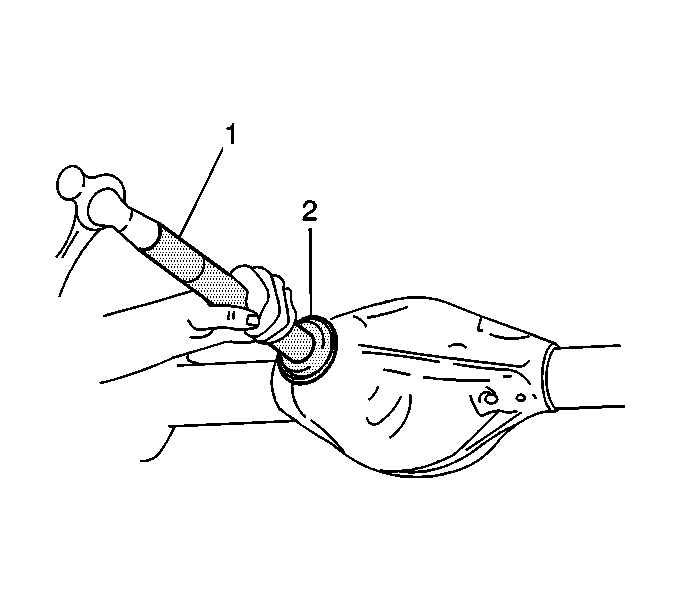
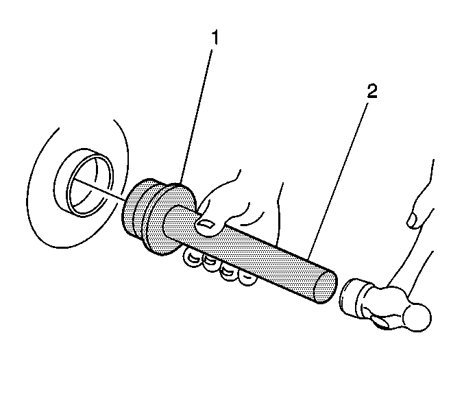
- Install the outer pinion bearing cup using the J 8611-01 (2) and the J 8092 (1).
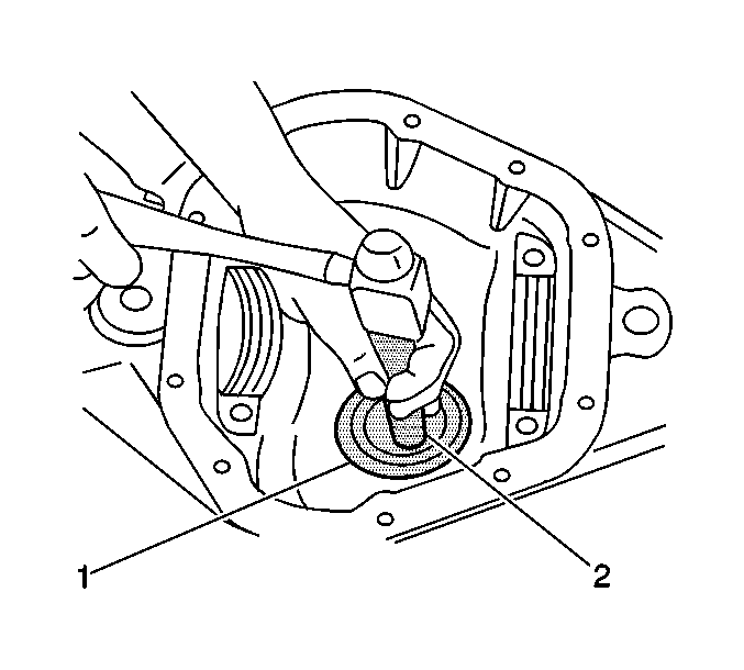
- Install the inner pinion bearing cup using the J 8608 (1) and the J 8092 (2).
- Determine the selective shim thickness for the pinion. Refer to Pinion Depth Adjustment .
- Install the selective shim between the inner pinion bearing and the shoulder on the gear.
- Install the inner pinion bearing using the J 24433 .
- Install a new collapsible spacer.
- Lubricate the pinion bearings with axle lubricant. Use the proper fluid. Refer to Fluid and Lubricant Recommendations in Maintenance and Lubrication.
- Install the pinion into the axle housing.
- Install the outer pinion bearing onto the pinion.
- Install a new seal using the J 22388 .
- Apply sealant, GM P/N 12346004 or equivalent, to the splines of the pinion yoke.
- Install the pinion yoke.
- Seat the pinion yoke onto the pinion shaft by tapping it with a soft-faced hammer until a few pinion shaft threads show through the yoke.
- Install the washer and a new pinion nut.
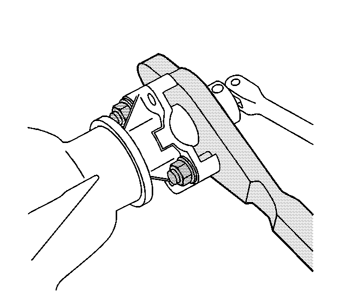
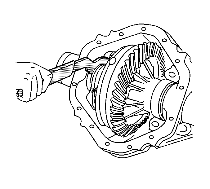
- Install the J 8614-01 onto the pinion yoke as shown.
- Tighten the pinion nut while holding the J 8614-01 .
- Lubricate the differential side bearings with axle lubricant. Use the proper fluid. Refer to Fluid and Lubricant Recommendations in Maintenance and Lubrication.
- Place the differential case, with the bearing cups installed, into the axle housing.
- Install the bearing caps and the bolts.
- Adjust the differential side bearing preload. Refer to Differential Carrier Bearing Preload Adjustment .
- Measure the rotating torque of the pinion. Compare this measurement with the rotating torque recorded during removal.
- Once the specified torque is obtained, rotate the pinion several times to ensure the bearings have seated. Recheck the rotating torque and adjust if necessary.
- Adjust the backlash. Refer to Backlash Adjustment .
- Perform a gear tooth contact pattern check. Refer to Gear Tooth Contact Pattern Inspection .
- Tighten the bearing cap bolts.
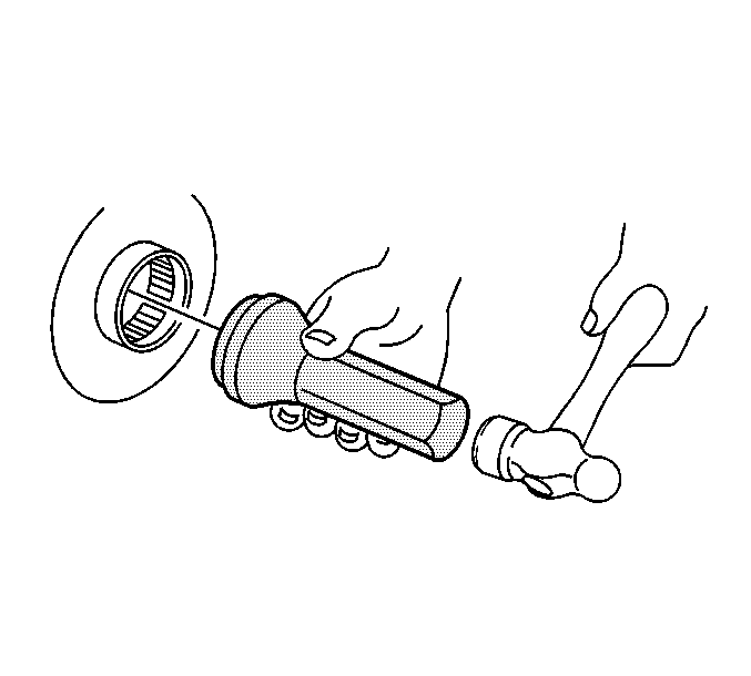
- Install the axle shaft bearing using the J 23690 (1) and the J 8092 (2).
- Drive the axle shaft bearing into the axle housing until the tool bottoms against the tube.
- Install the axle shaft seal using the J 21128 .
- Drive the tool into the bore until the axle shaft seal bottoms flush with the tube.
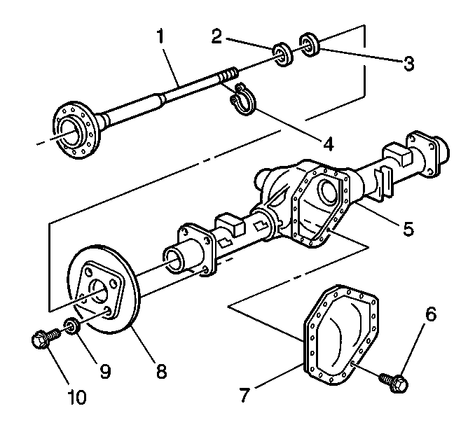
- Install the axle shaft (1) into the housing (5).
- Slide the axle shaft (1) into place allowing the splines to engage the differential side gear.
- On axles without a locking differential, place the lock (4) on the button end of the axle shaft (1).
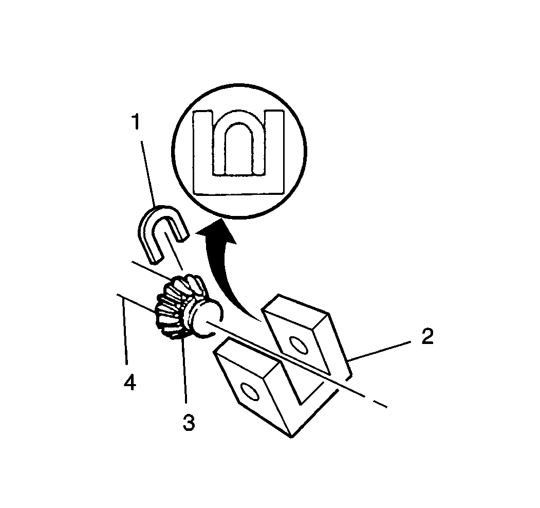
- On axles with a locking differential, keep the pinion shaft partially withdrawn.
- On axles with a locking differential, place the lock (1) on the axle shaft (3) so that the ends are flush with the thrust block (2).
- Pull the shaft flange outward in order to seat the lock in the differential gear.
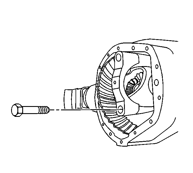
- Align the hole in the pinion shaft with the bolt hole in the differential case.
- Install the new pinion shaft locking bolt.
- Install the rear axle housing cover (2) and a new gasket.
- Install the new rear axle housing cover bolts (1).
- Install the drain plug.
- Fill the axle using the proper fluid. Refer to Approximate Fluid Capacities and Fluid and Lubricant Recommendations in Maintenance and Lubrication.
- Install the fill plug.
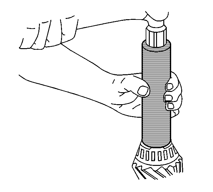
Press the bearing on until the cone seats on the pinion shim.
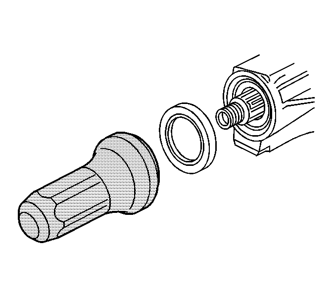
Align the marks make during removal.
Notice: Do not hammer the pinion flange/yoke onto the pinion shaft. Pinion components may be damaged if the pinion flange/yoke is hammered onto the pinion shaft.
Notice: Use the correct fastener in the correct location. Replacement fasteners must be the correct part number for that application. Fasteners requiring replacement or fasteners requiring the use of thread locking compound or sealant are identified in the service procedure. Do not use paints, lubricants, or corrosion inhibitors on fasteners or fastener joint surfaces unless specified. These coatings affect fastener torque and joint clamping force and may damage the fastener. Use the correct tightening sequence and specifications when installing fasteners in order to avoid damage to parts and systems.
Important: If the rotating torque is exceeded, the pinion will have to be removed and a new collapsible spacer installed.
Tighten
Tighten the nut until the pinion end play is just taken up. Rotate the
pinion while tightening the nut to seat the bearings.
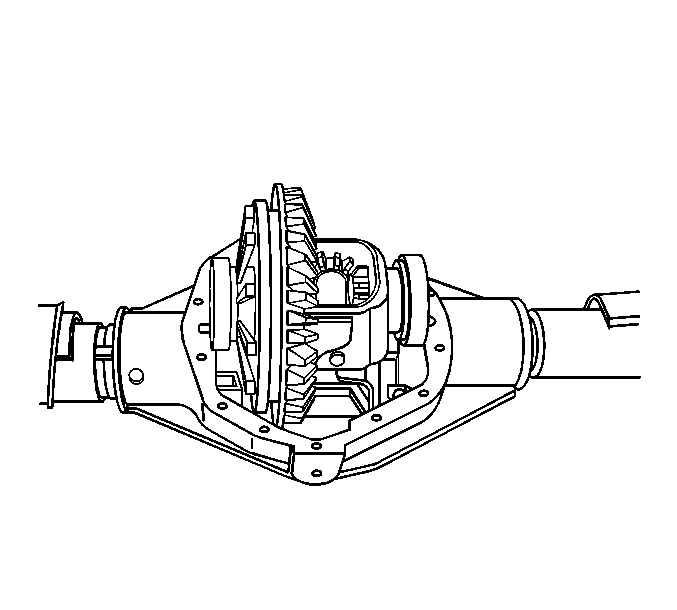
Do not torque the bearing cap bolts at this time.
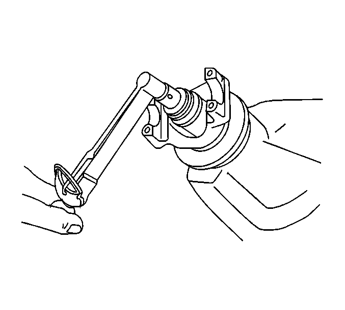
Tighten
Tighten the nut in small increments, as needed, until the rotating torque
is 0.40-0.57 N·m (3-5 lb in) greater
than the rotating torque recorded during removal.
Tighten
Tighten the bearing cap bolts to 75 N·m (55 lb ft).
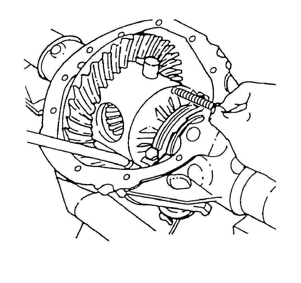
Important: Carefully insert the axle shaft in order to not damage the seal.
Tighten
Tighten the pinion shaft locking bolt to 36 N·m (27 lb ft).
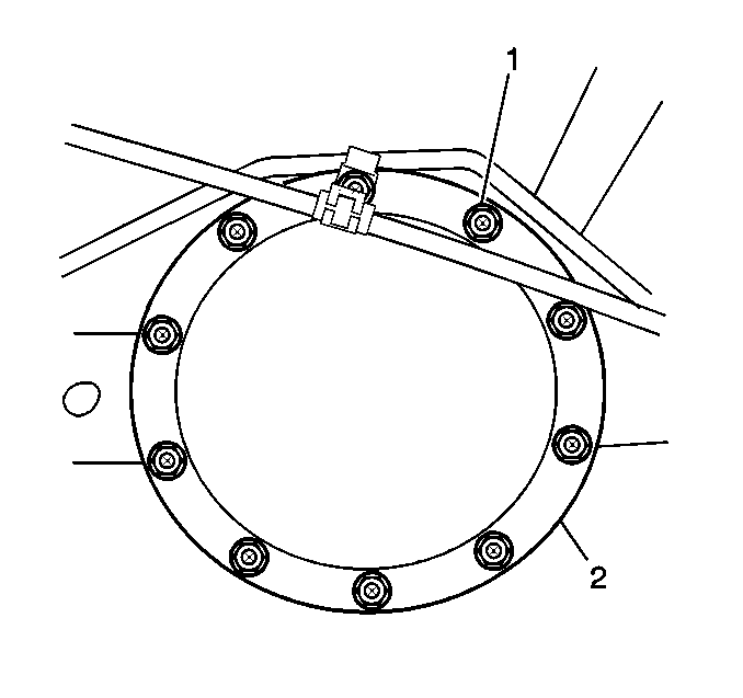
Important: Do not reuse the rear axle housing cover bolts.
Tighten
Tighten the rear housing cover bolts in a crosswise pattern to 40 N·m
(30 lb ft).
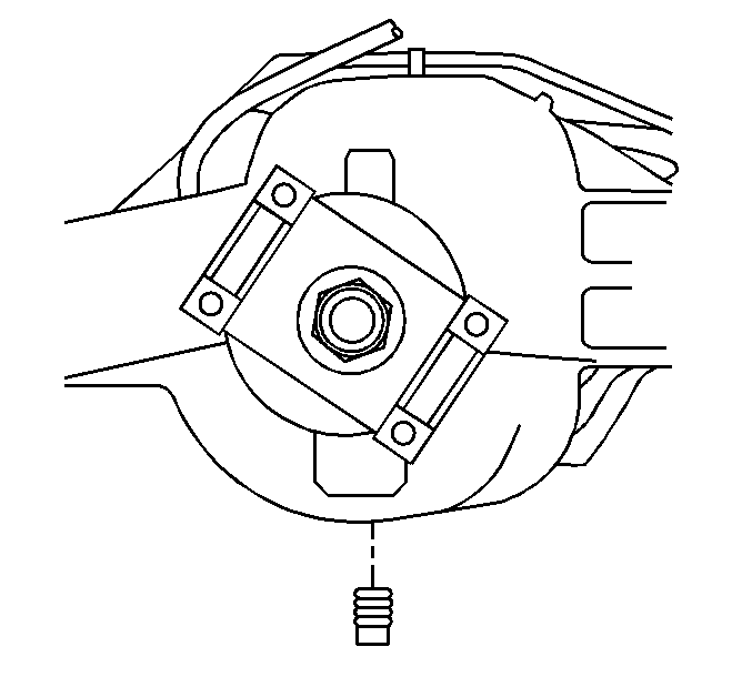
Tighten
Tighten the drain plug to 33 N·m (24 lb ft).
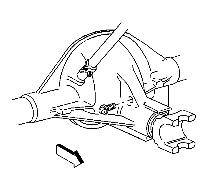
Tighten
Tighten the fill plug to 33 N·m (24 lb ft).
Rear Axle Assemble 9.5 Inch Axle
Tools Required
| • | J 7818 Inner Bearing Race Installer |
| • | J 8092 Driver Handle |
| • | J 8614-01 Flange/Pulley Holding Tool |
| • | J 22306 Rear Pinion Bearing Cup Installer |
| • | J 22388 Pinion Oil Seal Installer-Rear |
| • | J 24429 Side Bearing Backlash Spanner |
| • | J 29709 Wheel Bearing Installer |
| • | J 29713 Axle Shaft Seal Installer |
| • | J 36614 Inner Pinion Bearing Installer |
- Install the outer pinion bearing cup using the J 7818 (2) and the J 8092 (1).
- Install the inner pinion bearing cup using the J 22306 (1) and the J 8092 (2).
- Determine the selective shim thickness for the pinion. Refer to Pinion Depth Adjustment .
- Install the selective shim between the inner pinion bearing and the shoulder on the gear.
- Install the inner pinion bearing using the J 36614 .
- Install a new collapsible spacer.
- Lubricate the pinion bearings with axle lubricant. Use the proper fluid. Refer to Fluid and Lubricant Recommendations in Maintenance and Lubrication.
- Install the pinion into the axle housing.
- Install the outer pinion bearing onto the pinion.
- Install a new seal using the J 22388 .
- Apply sealant, GM P/N 12346004 or equivalent, to the splines of the pinion yoke.
- Install the pinion yoke.
- Seat the pinion yoke onto the pinion shaft by tapping it with a soft-faced hammer until a few pinion shaft threads show through the yoke.
- Install the washer and a new pinion nut.
- Install the J 8614-01 onto the pinion yoke as shown.
- Tighten the pinion nut while holding the J 8614-01 .
- Lubricate the differential side bearings with axle lubricant. Use the proper fluid. Refer to Fluid and Lubricant Recommendations in Maintenance and Lubrication.
- Place the differential case, with the bearing cups installed, into the axle housing.
- Install the bearing caps and the bolts.
- Turn the adjuster using the J 24429 until snug against the differential.
- Adjust the differential side bearing preload. Refer to Differential Carrier Bearing Preload Adjustment .
- Measure the rotating torque of the pinion. Compare this measurement with the rotating torque recorded during removal.
- Once the specified torque is obtained, rotate the pinion several times to ensure the bearings have seated. Recheck the rotating torque and adjust if necessary.
- Adjust the backlash. Refer to Backlash Adjustment .
- Perform a gear tooth contact pattern check. Refer to Gear Tooth Contact Pattern Inspection .
- Tighten the bearing cap bolts.
- Install the differential adjuster nut lock.
- Install the differential adjuster nut lock bolt.
- Install the axle shaft bearing using the J 29709 (1) and the J 8092 (2).
- Drive the axle shaft bearing into the axle housing until the tool bottoms against the tube.
- Install the axle shaft seal using the J 29713 .
- Drive the tool into the bore until the axle shaft seal bottoms flush with the tube.
- Install the axle shaft (1) into the housing (5).
- Slide the axle shaft (1) into place allowing the splines to engage the differential side gear.
- On axles without a locking differential, place the lock (4) on the button end of the axle shaft (1).
- On axles with a locking differential, keep the pinion shaft partially withdrawn.
- On axles with a locking differential, place the lock (1) on the axle shaft (3) so that the ends are flush with the thrust block (2).
- Pull the shaft flange outward in order to seat the lock in the differential gear.
- Align the hole in the pinion shaft with the bolt hole in the differential case.
- Install the new pinion shaft locking bolt.
- Install the rear axle housing cover (2) and a new gasket.
- Install the new rear axle housing cover bolts (1).
- Install the drain plug.
- Fill the axle using the proper fluid. Refer to Approximate Fluid Capacities and Fluid and Lubricant Recommendations in Maintenance and Lubrication.
- Install the fill plug.


Press the bearing on until the cone seats on the pinion shim.

Align the marks make during removal.
Notice: Do not hammer the pinion flange/yoke onto the pinion shaft. Pinion components may be damaged if the pinion flange/yoke is hammered onto the pinion shaft.

Notice: Use the correct fastener in the correct location. Replacement fasteners must be the correct part number for that application. Fasteners requiring replacement or fasteners requiring the use of thread locking compound or sealant are identified in the service procedure. Do not use paints, lubricants, or corrosion inhibitors on fasteners or fastener joint surfaces unless specified. These coatings affect fastener torque and joint clamping force and may damage the fastener. Use the correct tightening sequence and specifications when installing fasteners in order to avoid damage to parts and systems.
Important: If the rotating torque is exceeded, the pinion will have to be removed and a new collapsible spacer installed.
Tighten
Tighten the nut until the pinion end play is just taken up. Rotate the
pinion while tightening the nut to seat the bearings.

Support the case in order to keep the case from falling out of the axle housing.

Do not torque the bearing cap bolts at this time.

Tighten
Tighten the nut in small increments, as needed, until the rotating torque
is 0.40-0.57 N·m (3-5 lb in) greater
than the rotating torque recorded during removal.
Tighten
Tighten the bearing cap bolts to 85 N·m (63 lb ft).
Tighten
Tighten the differential adjuster nut lock bolt to 26 N·m
(19 lb ft).


Important: Carefully insert the axle shaft in order to not damage the seal.


Tighten
Tighten the pinion shaft locking bolt to 50 N·m (37 lb ft).

Important: Do not reuse the rear axle housing cover bolts.
Tighten
Tighten the rear housing cover bolts in a crosswise pattern to 40 N·m
(30 lb ft).

Tighten
Tighten the drain plug to 33 N·m (24 lb ft).

Tighten
Tighten the fill plug to 33 N·m (24 lb ft).
Rear Axle Assemble 11.5 Inch Axle
Tools Required
| • | J 2222-C Wheel Bearing Nut Wrench |
| • | J 8092 Driver Handle |
| • | J 8608 Outer Pinion Bearing Race Installer |
| • | J 8614-01 Flange/Pulley Holding Tool |
| • | J 44412 Pinion Bearing Installer |
| • | J 44414 Rear Axle Pinion Oil Seal Installer |
| • | J 44417 Rear Pinion Bearing Race Installer |
| • | J 24429 Side Bearing Backlash Adjuster Wrench |
- Install the outer pinion bearing cup using the J 8608 (1) and the J 8092 (2).
- Install the inner pinion bearing cup using the J 44417 (1) and the J 8092 (2).
- Determine the selective shim thickness for the pinion. Refer to Pinion Depth Adjustment .
- Install the selective shim between the inner pinion bearing and the shoulder on the gear.
- Install the inner pinion bearing using the J 44412 .
- Install a new collapsible spacer.
- Lubricate the pinion bearings with axle lubricant. Use the proper fluid. Refer to Fluid and Lubricant Recommendations in Maintenance and Lubrication.
- Install the pinion into the axle housing.
- Install the outer pinion bearing onto the pinion.
- Install a new seal using the J 44414 .
- Apply sealant (GM P/N 12346004 or equivalent) to the splines of the pinion yoke.
- Install the pinion yoke.
- Seat the pinion yoke onto the pinion shaft by tapping it with a soft-faced hammer until a few pinion shaft threads show through the yoke.
- Install the washer and a new pinion nut.
- Install the J 8614-01 onto the pinion yoke as shown.
- Tighten the pinion nut while holding the J 8614-01 .
- Install the differential bearing adjusters.
- Lubricate the differential side bearings with axle lubricant. Use the proper fluid. Refer to Fluid and Lubricant Recommendations in Maintenance and Lubrication.
- Place the differential case, with the bearing cups installed, into the axle housing.
- Install the bearing caps and the bolts.
- Turn the adjusters evenly on each side using the J 24429 until snug against the differential.
- Adjust the differential side bearing preload. Refer to Differential Carrier Bearing Preload Adjustment .
- Measure the rotating torque of the pinion. Compare this measurement with the rotating torque recorded during removal.
- Once the specified torque is obtained, rotate the pinion several times to ensure the bearings have seated. Recheck the rotating torque and adjust if necessary.
- Adjust the backlash. Refer to Backlash Adjustment .
- Perform a gear tooth contact pattern check. Refer to Gear Tooth Contact Pattern Inspection .
- Tighten the bearing cap bolts.
- Install the differential adjuster nut locks.
- Install the differential bearing adjuster nut lock bolts.
- Apply a light coat of high melting point EP bearing lubricant to the axle housing spindle.
- Install the wheel hub to the axle housing.
- Install the adjusting nut to the hub using the J 2222-C .
- Adjust the wheel bearings. Refer to Wheel Bearing Adjustment .
- Install the gasket onto the axle shaft.
- Install the gasket and the axle shaft into the axle tube.
- Install the axle flange bolts.
- Install the rear axle housing cover (2) and a new gasket.
- Install the new rear axle housing cover bolts (1).
- Install the drain plug.
- Fill the axle using the proper lubricant. Refer to Approximate Fluid Capacities and Fluid and Lubricant Recommendations in Maintenance and Lubrication.
- Install the seal and the fill plug.


Press the bearing on until the cone seats on the pinion shim.

Align the marks made during removal.
Notice: Do not hammer the pinion flange/yoke onto the pinion shaft. Pinion components may be damaged if the pinion flange/yoke is hammered onto the pinion shaft.

Notice: Use the correct fastener in the correct location. Replacement fasteners must be the correct part number for that application. Fasteners requiring replacement or fasteners requiring the use of thread locking compound or sealant are identified in the service procedure. Do not use paints, lubricants, or corrosion inhibitors on fasteners or fastener joint surfaces unless specified. These coatings affect fastener torque and joint clamping force and may damage the fastener. Use the correct tightening sequence and specifications when installing fasteners in order to avoid damage to parts and systems.
Important: If the rotating torque is exceeded, the pinion will have to be removed and a new collapsible spacer installed.
Tighten
Tighten the nut until the pinion end play is just taken up. Rotate the
pinion while tightening the nut to seat the bearings.


Do not torque the bearing cap bolts at this time.

Tighten
Tighten the nut in small increments, as needed, until the rotating torque
is 0.40-0.57 N·m (3-5 lb in) greater
than the rotating torque recorded during removal.
Tighten
Tighten the bearing cap bolts to 207 N·m (153 lb ft).
Tighten
Tighten the differential bearing adjuster nut lock bolts to 27 N·m
(20 lb ft).
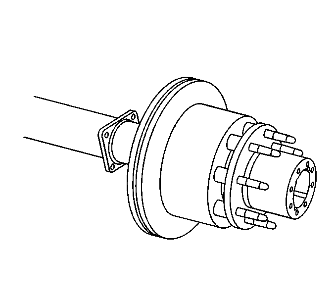
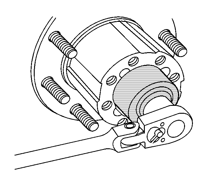
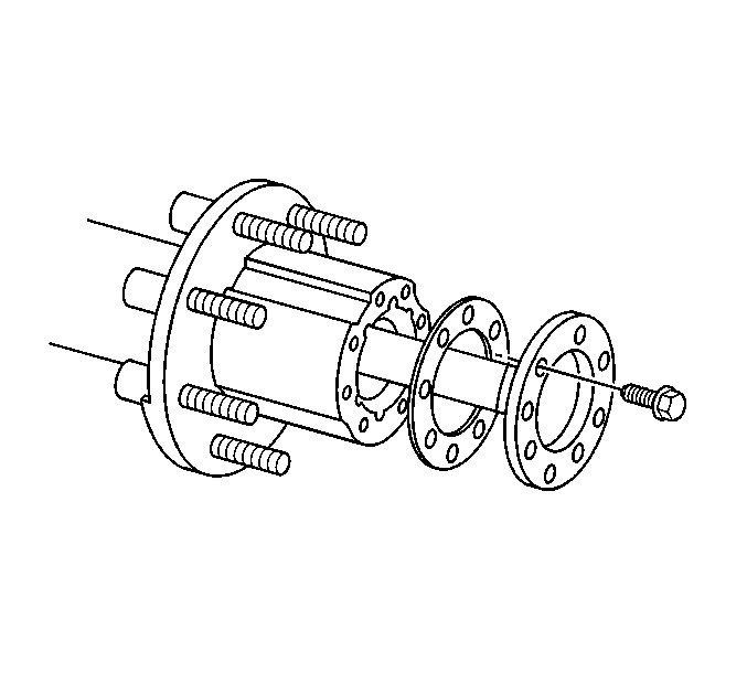
| 35.1. | Ensure the shaft splines mesh into the differential side gear. |
| 35.2. | Align the holes in the axle flange and the gasket with the holes in the hub. |
Tighten
Tighten the axle flange bolts to 200 N·m (148 lb ft).

Important: Do not reuse the rear axle housing cover bolts.
Tighten
Tighten the rear housing cover bolts in a crosswise pattern to 40 N·m
(30 lb ft).
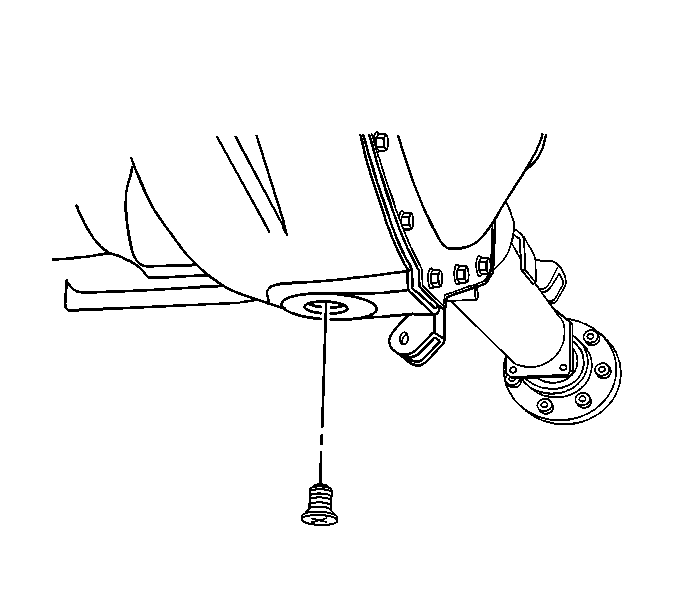
Tighten
Tighten the drain plug to 33 N·m (24 lb ft).
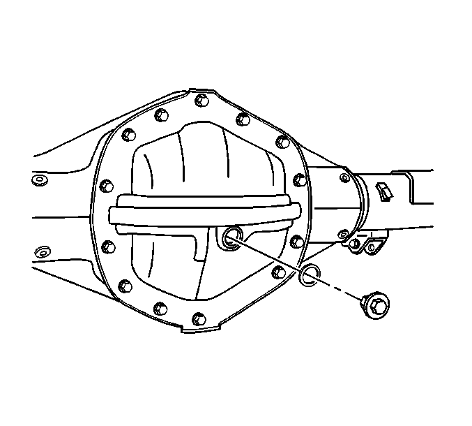
Tighten
Tighten the fill plug to 33 N·m (24 lb ft).
