Power Steering Gear Inlet Pipe/Hose Replacement With Gas Hydroboost
Removal Procedure
- Install a drain pan under the vehicle.
- Remove the power steering gear inlet hose (1) from the brake booster.
- Remove the power steering gear inlet hose from the power steering gear.
- Remove the power steering gear inlet hose from the vehicle.
Notice: Do not start the vehicle with any power steering gear inlet or outlet hoses disconnected. When disconnected, plug or cap all openings of components. Failure to do so could result in contamination or loss of power steering fluid and damage to the system.
Installation Procedure
- Route the hose in the same position the hose occupied prior to removal.
- Install the power steering gear inlet hose (1) to the brake booster (2). Hand tighten only.
- Install the power steering gear inlet hose to the power steering gear.
- Remove the drain pan from under the vehicle.
- Bleed the power steering system. Refer to Power Steering System Bleeding .
Notice: The inlet and outlet hoses must not be twisted during installation. Do not bend or distort the inlet or outlet hoses to make installation easier. Failure to follow these procedures could result in component damage.
Notice: Refer to Fastener Notice in the Preface section.
Tighten
Tighten both power steering gear inlet hose fittings to 28 N·m (20 lb ft).
Power Steering Gear Inlet Pipe/Hose Replacement Rack and Pinion
Removal Procedure
Notice: Do not start the vehicle with any power steering gear inlet or outlet hoses disconnected. When disconnected, plug or cap all openings of components. Failure to do so could result in contamination or loss of power steering fluid and damage to the system.
- Remove the power steering inlet hose (2) from the power steering pump (1).
- Remove the power steering inlet hose (2) from the power steering gear (3).
Installation Procedure
- Connect the power steering inlet hose (2) to the power steering gear (3).
- Connect the power steering inlet hose (2) to the power steering pump (1).
- Bleed the power steering system. Refer to Power Steering System Bleeding .
- Inspect all the hose connections for leaks.
Notice: Use the correct fastener in the correct location. Replacement fasteners must be the correct part number for that application. Fasteners requiring replacement or fasteners requiring the use of thread locking compound or sealant are identified in the service procedure. Do not use paints, lubricants, or corrosion inhibitors on fasteners or fastener joint surfaces unless specified. These coatings affect fastener torque and joint clamping force and may damage the fastener. Use the correct tightening sequence and specifications when installing fasteners in order to avoid damage to parts and systems.
Tighten
Tighten the hose connections to 28 N·m (20 lb ft.)
Power Steering Gear Inlet Pipe/Hose Replacement Without Hydroboost
Removal Procedure
- Raise the vehicle. Refer to Lifting and Jacking the Vehicle .
- Remove the engine protection shield. Refer to Engine Protection Shield Replacement .
- Install a drain pan under the vehicle.
- Remove the power steering gear inlet hose (3) from the power steering pump (1).
- Remove the power steering gear inlet hose from the power steering gear.
- Remove the power steering gear inlet hose from the vehicle.
Notice: Do not start the vehicle with any power steering gear inlet or outlet hoses disconnected. When disconnected, plug or cap all openings of components. Failure to do so could result in contamination or loss of power steering fluid and damage to the system.
Installation Procedure
- Route the hose in the same position the hose occupied prior to removal.
- Install the power steering gear inlet hose (3) to the power steering pump (1). Hand tighten only.
- Install the power steering gear inlet hose to the power steering gear.
- Remove the drain pan from under the vehicle.
- Install the engine protection shield. Refer to Engine Protection Shield Replacement .
- Lower the vehicle.
- Bleed the power steering system. Refer to Power Steering System Bleeding .
Notice: The inlet and outlet hoses must not be twisted during installation. Do not bend or distort the inlet or outlet hoses to make installation easier. Failure to follow these procedures could result in component damage.
Notice: Refer to Fastener Notice in the Preface section.
Tighten
Tighten both power steering gear inlet hose fittings to 28 N·m (20 lb ft).
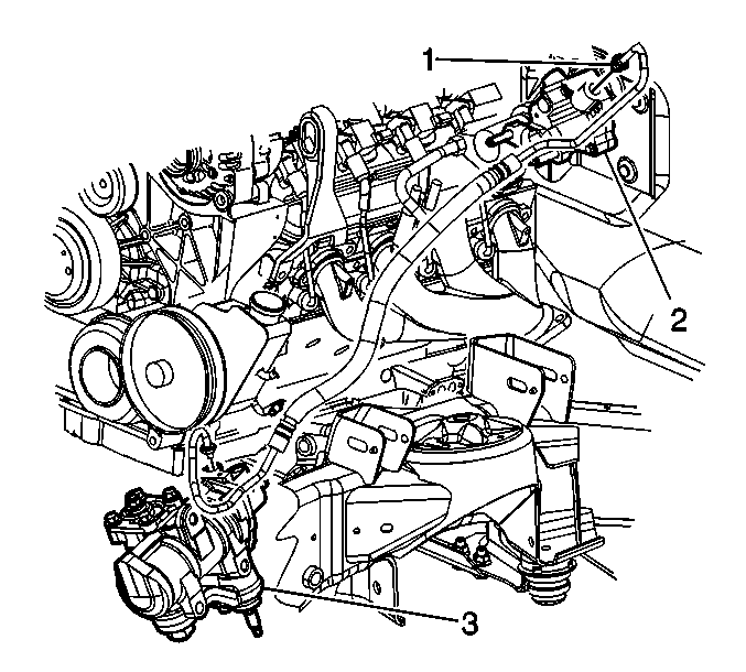
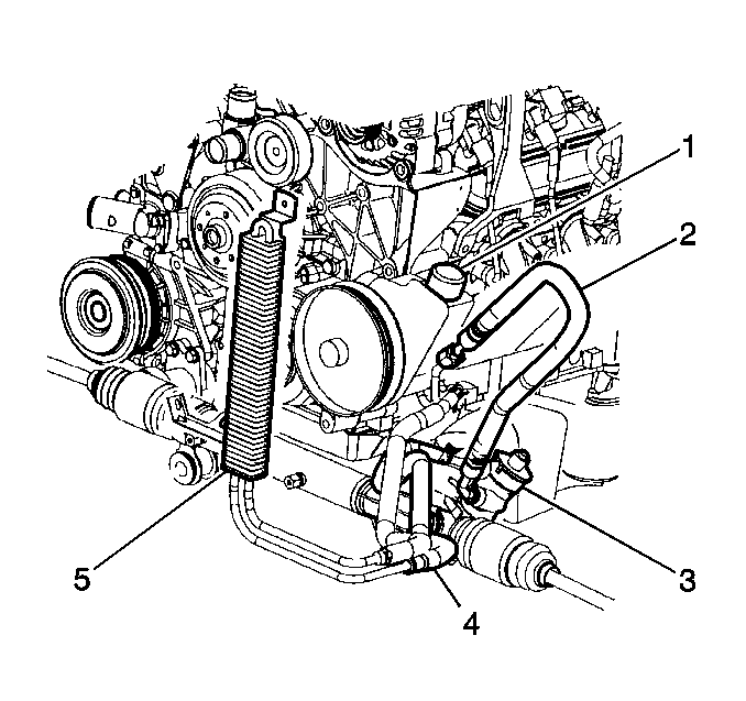
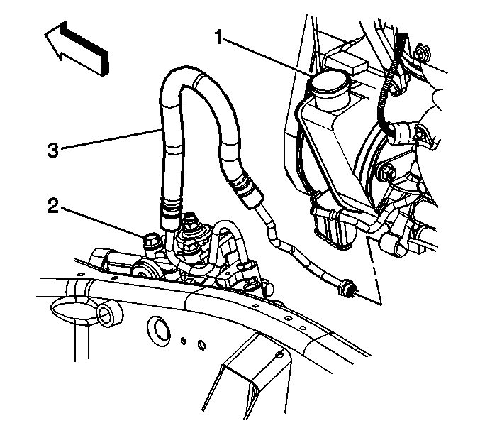
Power Steering Gear Inlet Pipe/Hose Replacement With Diesel Hydroboost
Removal Procedure
- Raise the vehicle. Refer to Lifting and Jacking the Vehicle.
- Remove the LH front tire assembly. Refer to Tire and Wheel Removal and Installation.
- Remove the LH wheelhouse panel. Refer to Wheelhouse Panel Replacement.
- Working through the left wheelhouse, loosen the charged air cooler inlet duct clamp (1) at the charged air cooler.
- Disconnect the charged air cooler from the elbow connection (2) and reposition the left charged air cooler inlet duct for access to the power steering gear inlet line connection at the gear.
- Remove the engine protection shield. Refer to Engine Protection Shield Replacement.
- Install a drain pan under the vehicle.
- Remove the brake booster inlet clamp bolt from the frame rail.
- Remove the power steering gear inlet hose from the power steering gear.
- Lower the vehicle.
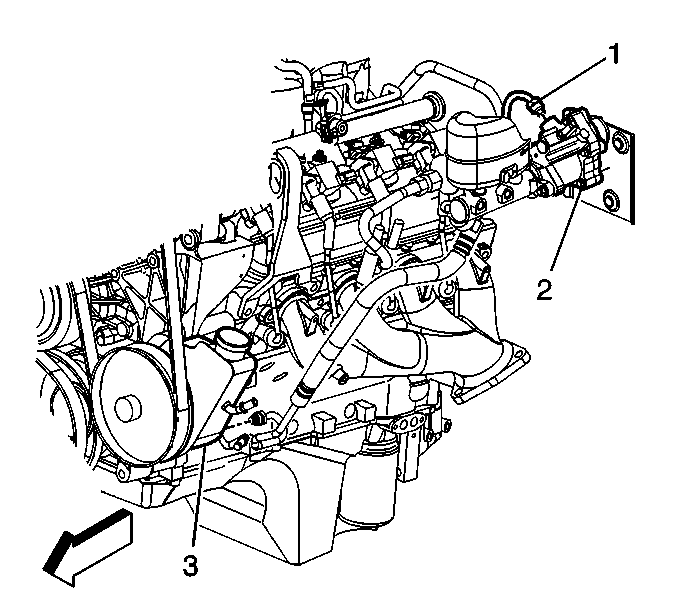
- Remove the power steering gear inlet hose (1) from the brake booster.
- Remove the power steering gear inlet hose from the vehicle.
Notice: Refer to Power Steering Hose Disconnected Notice in the Preface section.
Notice: Refer to Power Steering Hose Disconnected Notice in the Preface section.
Installation Procedure
- Route the hose in the same position the hose occupied prior to removal.
- Install the power steering gear inlet hose (1) to the brake booster (2). Hand tighten only.
- Raise the vehicle.
- Install the power steering gear inlet hose (1) to the power steering gear (3) through the wheel well.
- Install the power steering gear inlet hose clamp bolt to the frame rail.
- Install the engine protection shield. Refer to Engine Protection Shield Replacement.
- Working through the left wheelhouse, connect the charged air cooler inlet duct (1) to the elbow.
- Tighten the charged air cooler outlet duct to intake hose clamp.
- Install the LH wheelhouse panel. Refer to Wheelhouse Panel Replacement.
- Install the LH front tire assembly. Refer to Tire and Wheel Removal and Installation.
- Lower the vehicle.
- Tighten the power steering gear inlet hose to brake booster.
- Install the power steering gear inlet hose to power steering gear.
- Install the brake booster inlet hose clamp bolt to frame rail.
- Remove the drain pan from under the vehicle.
- Bleed the power steering system. Refer to Power Steering System Bleeding.
Notice: Refer to Installing Hoses without Twists or Bends Notice in the Preface section.
Notice: Refer to Fastener Notice in the Preface section.
Tighten
Tighten the power steering gear inlet hose fitting to 28 N·m (21 lb ft).
Tighten
Tighten the power steering gear inlet hose clamp to 12 N·m (9 lb ft).
Important: Do not over tighten the charged air cooler pipe clamps. If the clamp is over tightened, the pipe may become distorted allowing separation of the hose from the pipe. Ensure the charged air cooler pipe/hoses are properly orientated.
Tighten
Tighten the clamps to 8 N·m (70 lb in).
Tighten
Tighten the power steering gear inlet hose fitting to 28 N·m (21 lb ft).
Tighten
Tighten both power steering gear inlet hose fittings to 28 N·m (21 lb ft).
Tighten
Tighten the brake booster inlet hose clamp bolt to 12 N·m (9 lb ft).
