For 1990-2009 cars only
Tools Required
| • | J 6133-A Bearing Race Installer |
| • | J 22873 Slide Hammer |
| • | J 36184 Press Tube Adapter |
| • | J 36373 Input Gear Ball Bearing Installer |
| • | J 36515 Assembly Pallet |
| • | J 36515-15 Mainshaft Adapter |
| • | J 36515-16 Countershaft Adapter |
| • | J 36850 TRANSJEL Lubricant |
| • | J 39924-1 Reverse Drag Seal Installer |
| • | J 39924-2 5th Gear Drag Seal Installer |
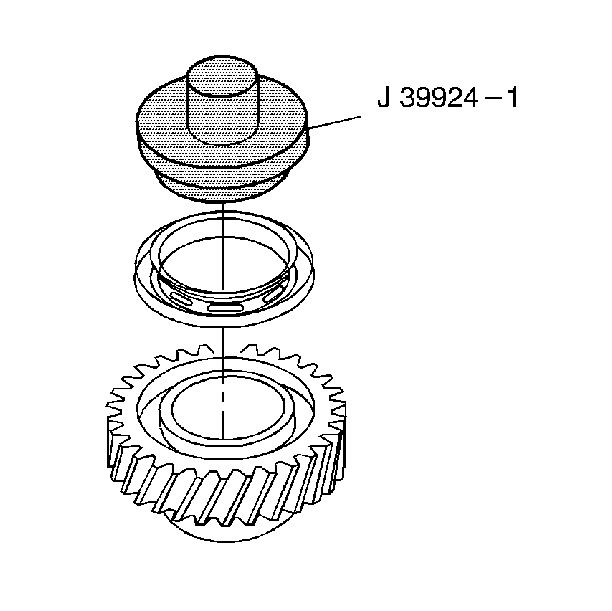
- Using the J 39924-1 , install the reverse speed gear drag seal.
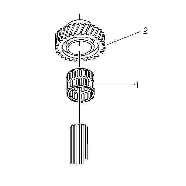
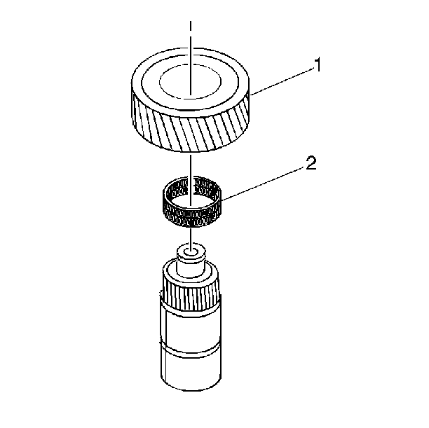
- Install the reverse speed gear needle bearing (1).
- Lubricate the reverse speed gear bearing with transmission fluid.
- Install the reverse speed gear (2).
- Install the 5th/Reverse speed gear synchronizer assembly using a hydraulic press and J 36184 .
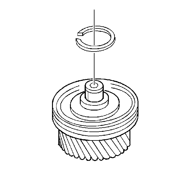
- Install a new 5th/Reverse synchronizer hub retaining ring.
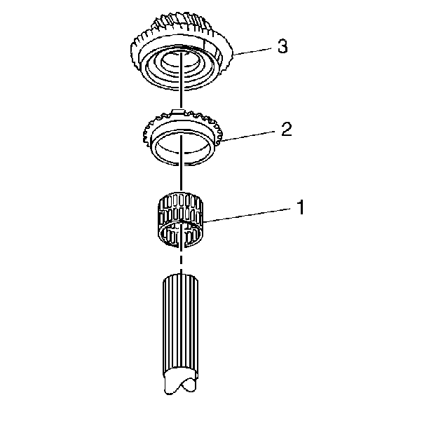
- Install the 5th speed gear needle bearing (1).
- Lubricate the bearing with transmission fluid.
- Install the synchronizer ring (2).
- Install the 5th speed gear (3).
- Install the 1st speed gear needle bearing assembly.
- Lubricate the bearing with transmission fluid.
- Install the following components:
- Install the 1st/2nd speed gear synchronizer assembly with both synchronizer rings.
- Install a new 1st/2nd gear synchronizer retaining ring.
- Install the following 2nd gear synchronizer components:
- Install the 2nd speed gear needle bearing (2).
- Lubricate the bearing with transmission fluid.
- Install the 2nd speed gear (1).
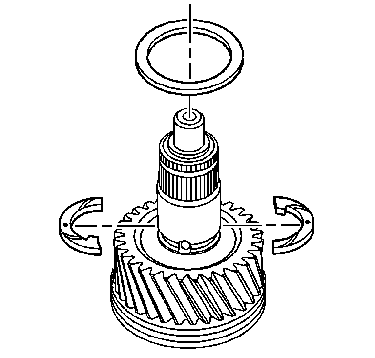
- Install the 2nd speed gear 2 piece thrust washer. Ensure that the dots on the thrust washer are facing up.
- Install the retainer ring. Ensure that the retainer ring is installed around the thrust washers.
- Install the following components:
- Install the 3rd/4th speed gear synchronizer assembly with both synchronizer rings. Ensure that the groove in the synchronizer ring faces upward.
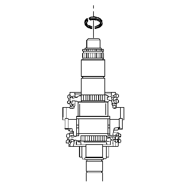
- Install a new mainshaft snap ring.
- Install the input shaft (1) on the assembly fixture J 36515-15 and J 36515 .
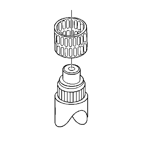
- Install the pilot bearing (2) in the input shaft (1).
- Install the synchronizer ring (3) on the input shaft (1).
- Install the mainshaft assembly (4) onto the input shaft (1).
- Install the following parts on the mainshaft and on the assembly fixture J 36515-16 :
- Install the countershaft bearing on the countershaft.
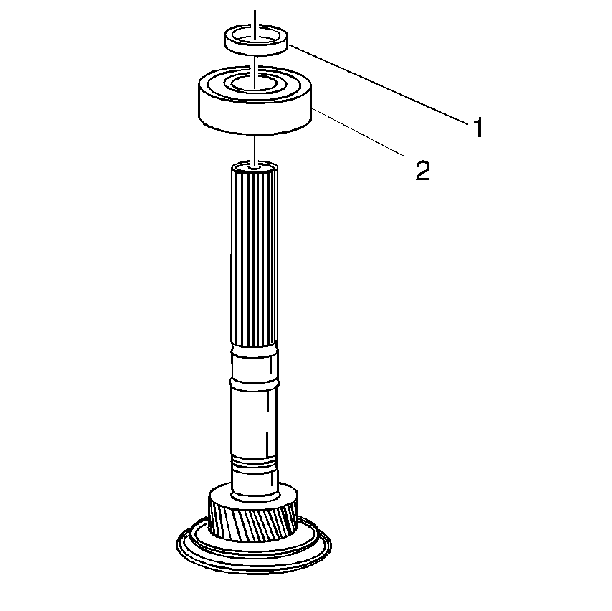
- If RWD vehicle, install the main shaft rear bearing (2) on the main shaft.
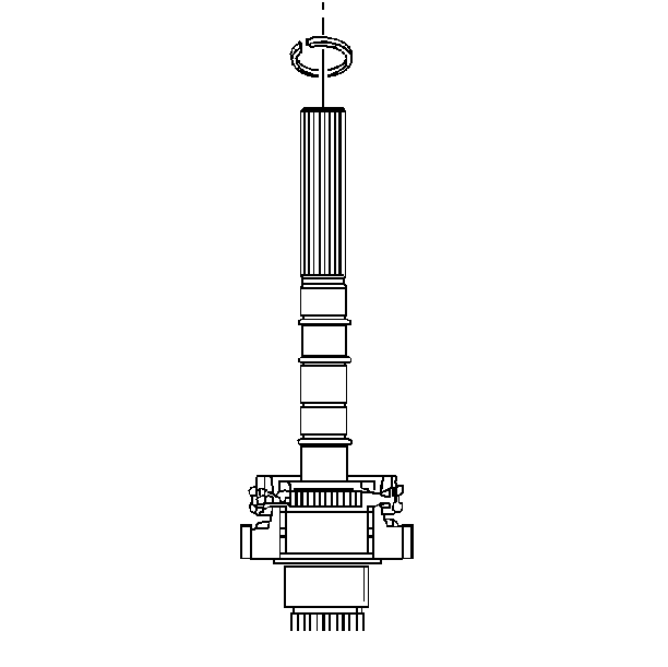
- Install a new main shaft rear bearing retaining ring (1).
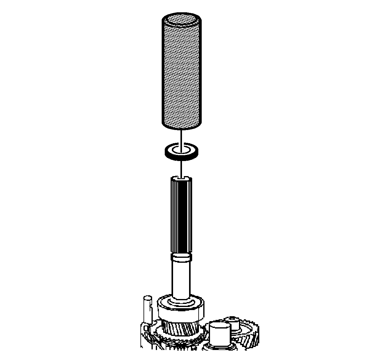
- If RWD vehicle, using J 6133-A , install the reluctor wheel onto the main shaft.
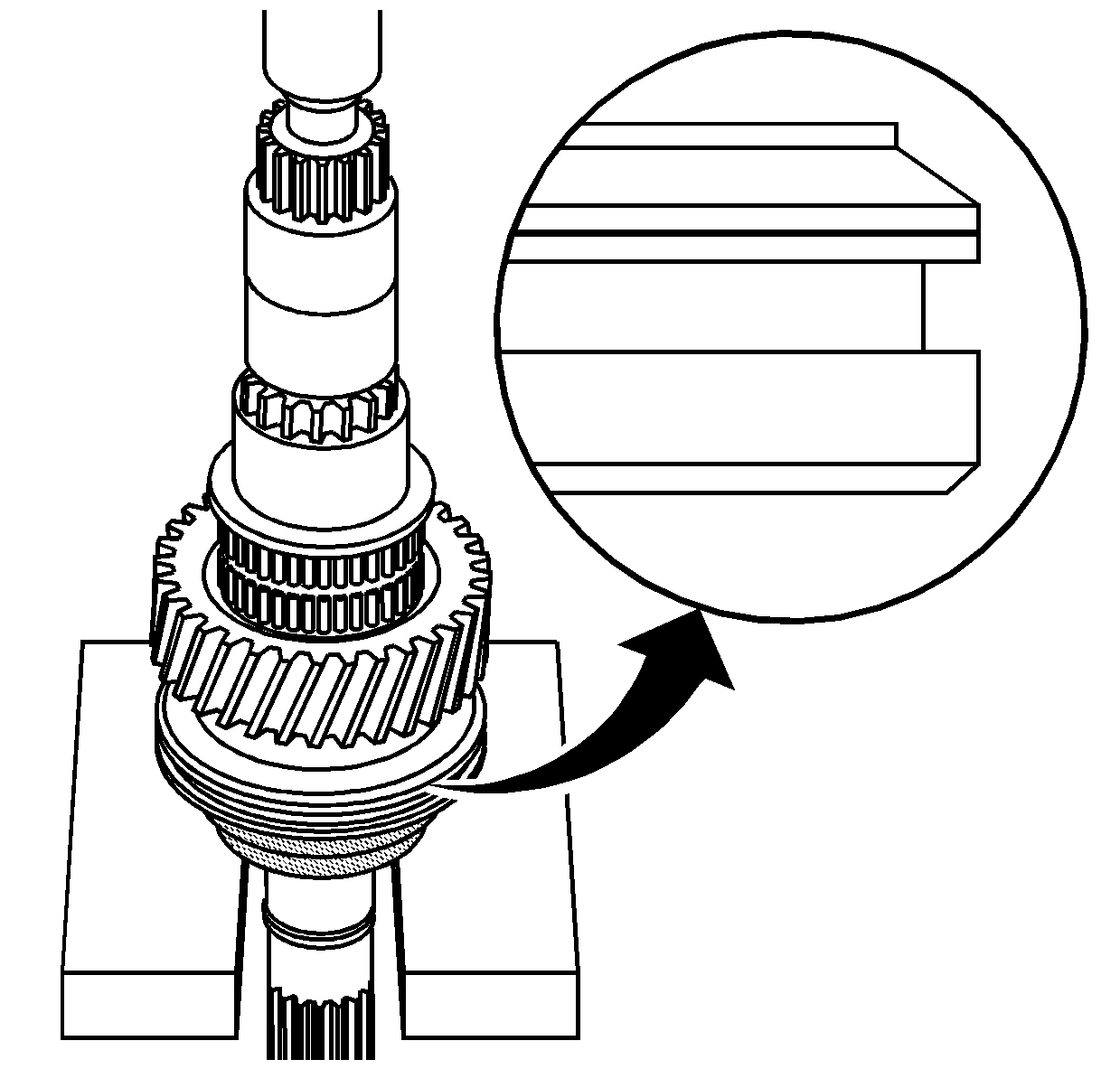
| 5.1. | Align the groove on the 5th/Reverse synchronizer sleeve towards the reverse gear. |
| 5.2. | Ensure the reverse synchronizer blocking ring is aligned to the synchronizer hub. |
Important: The groove on the outside of the synchronizer sleeve must go towards the 2nd speed gear. This prevents gear clash during 1st and 2nd speed gear shifts. The teeth of the sleeve have different angles.
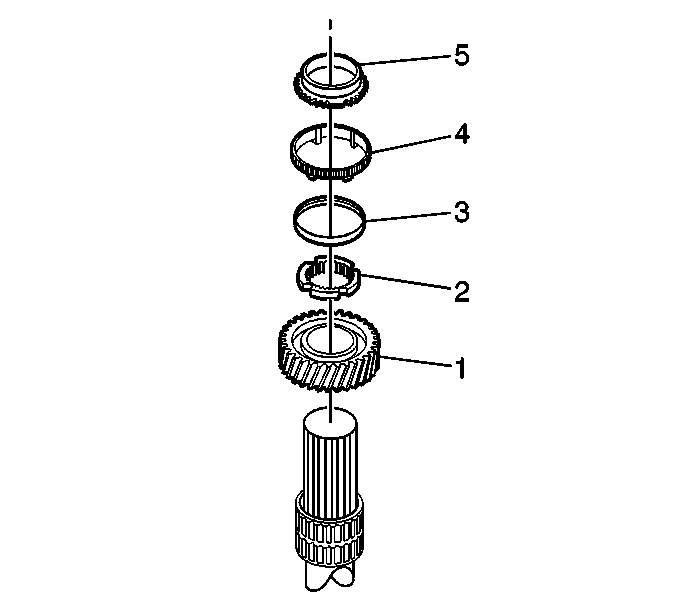
| 13.1. | The 1st speed gear (1) |
| 13.2. | The synchronizer interim ring (2) with the teeth up |
| 13.3. | The reactor cone (3) with the flat side towards 1st gear |
| 13.4. | The blocker ring (4) with the teeth down |
| 13.5. | The synchronizer cone (5) with the flat side down |
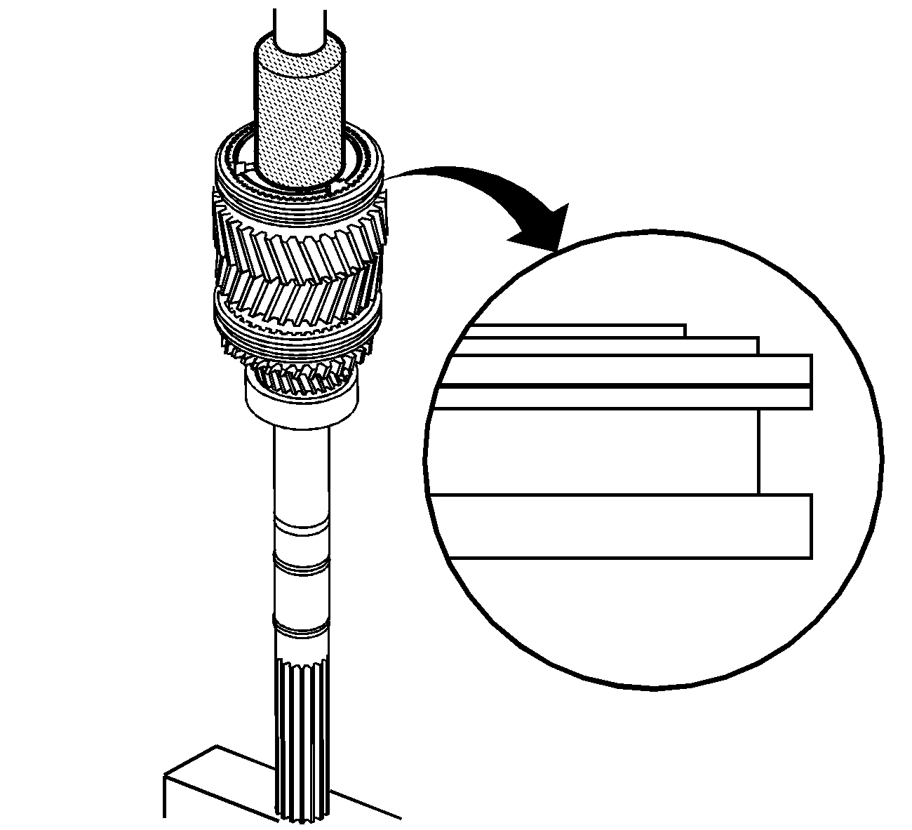
| 14.1. | Manually align and engage the splines of the synchronizer hub with the main shaft splines. |
| 14.2. | Using a hydraulic press, the J 22873 , press the synchronizer hub onto the main shaft. |
| 14.3. | Start the press operation. |
| 14.3.1. | Stop pressing before the tangs engage. |
| 14.3.2. | Lift and rotate the gear. |
| 14.3.3. | Engage the synchronizer ring. |
| 14.4. | Press the synchronizer until seated. |
| 14.5. | Remove all the metal shavings. |
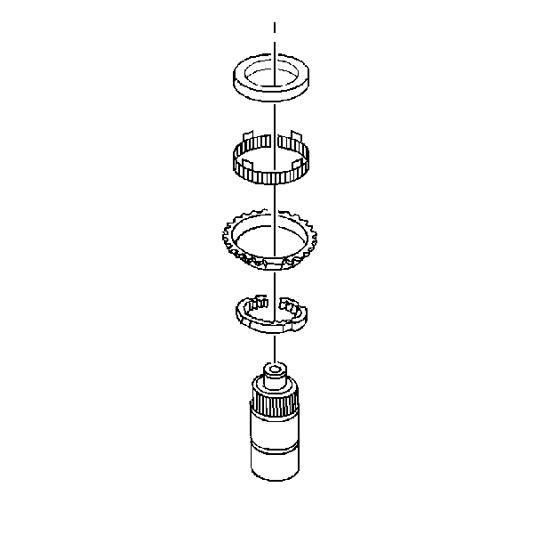
| 16.1. | The synchronizer cone with the flat up |
| 16.2. | The blocker ring with the tangs up |
| 16.3. | The reaction cone with the wide flat portion up |
| 16.4. | The interim ring |
Ensure that the synchronizer ring gear teeth are positioned toward the 1st gear.
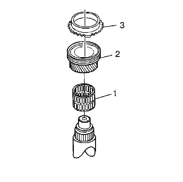
| 22.1. | The 3rd speed gear needle bearing (1) |
| 22.2. | The 3rd speed gear (2) |
| 22.3. | The synchronizer ring (3) |
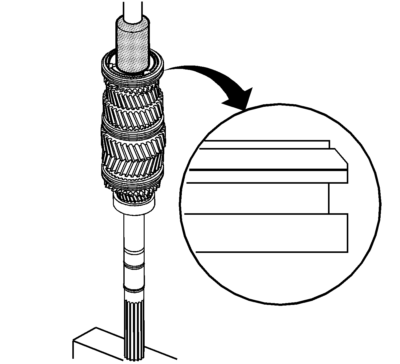
| 23.1. | Manually align and engage the splines of the synchronizer hub with the main shaft splines. |
| 23.2. | Using a hydraulic press, the J 36373 , press the synchronizer hub onto the main shaft. |
| 23.3. | Start the press operation. |
| 23.3.1. | Stop pressing before the tangs engage. |
| 23.3.2. | Lift and rotate the gear. |
| 23.3.3. | Engage the synchronizer ring. |
| 23.4. | Press the synchronizer until seated. |
| 23.5. | Remove all the metal shavings. |
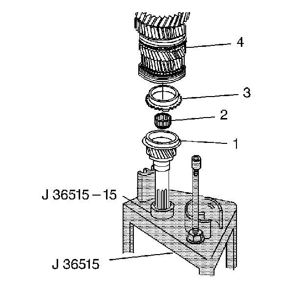
| 26.1. | Ensure the small diameter of the bearing is positioned toward the input shaft. |
| 26.2. | Lubricate the pilot bearing with J 36850 . |
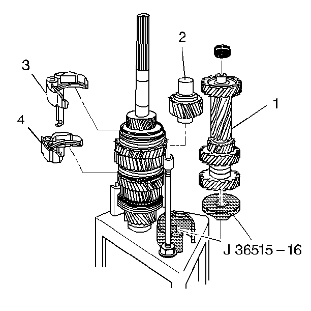
| 29.1. | The countershaft assembly (1) |
| 29.2. | The reverse idler assembly (2) |
| 29.3. | The 1st/2nd speed gear shift fork (3) |
| 29.4. | The 5th/Reverse speed gear shift fork (4) |
Use the J 36850 in order to retain the bearing.
The smaller diameter of the bearing cage is positioned toward the housing.
