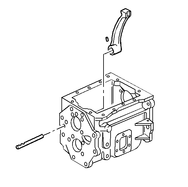
- Install the following
parts:
| 1.1. | The overdrive speed gear shift lever |
| 1.2. | The shift lever shaft |
The notches that retain the overdrive speed gear shift fork are to the
outside of the case.
| 1.3. | The shift lever retaining pin |
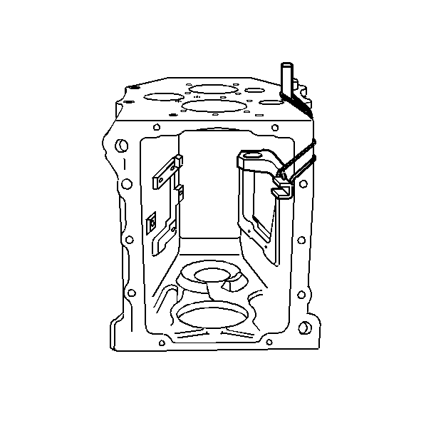
- Install a rubber band,
in order to hold the overdrive speed gear shift lever back out of the way.
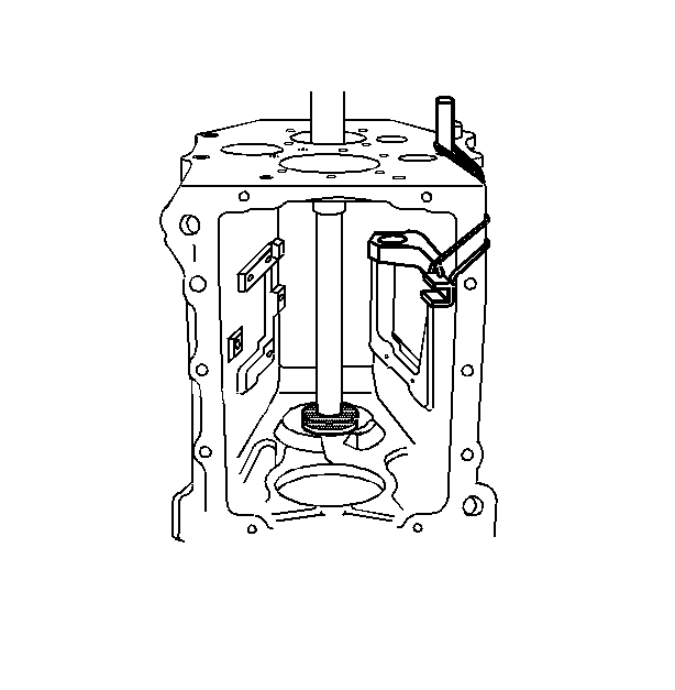
- Using the J 38856
, install the countershaft front bearing
cup.
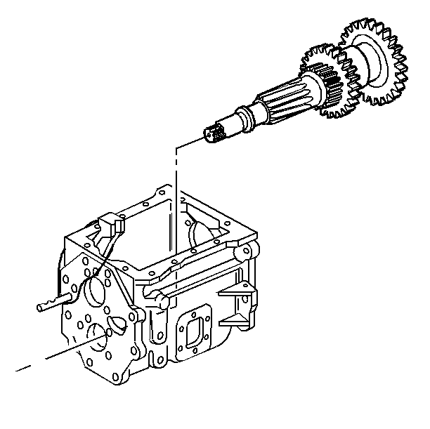
- Install the countershaft
assembly into the transmission case. Position the rear of the countershaft
into the rear countershaft bearing bore, then move the front of
the countershaft into position.
- Install the countershaft
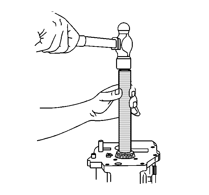
rear bearing, using the following procedure:
| 5.1. | Position the transmission case with the front of the case down. |
| 5.2. | Lift the countershaft, and place a block of wood between the front
of the countershaft and the transmission case. |
| 5.3. | Using the J 22828
, install the countershaft rear bearing. |
- Install the following
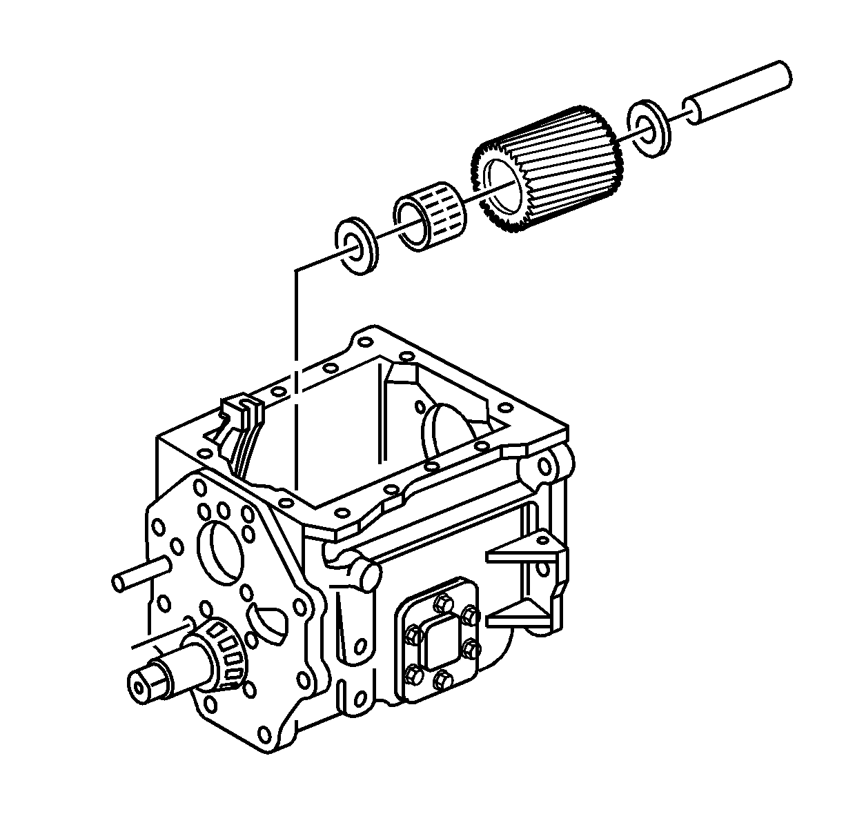
parts:
| 6.1. | The reverse idler gear |
| 6.4. | The reverse idler gear shaft |
The step on the shaft aligns toward the countershaft, and is installed
flush to the case.
- Position the transmission
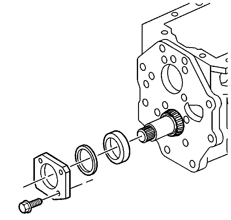
with the front of the case down.
- Position the countershaft in the countershaft front bearing cup.
- Install the countershaft rear bearing cup.
Notice: Use the correct fastener in the correct location. Replacement fasteners
must be the correct part number for that application. Fasteners requiring
replacement or fasteners requiring the use of thread locking compound or sealant
are identified in the service procedure. Do not use paints, lubricants, or
corrosion inhibitors on fasteners or fastener joint surfaces unless specified.
These coatings affect fastener torque and joint clamping force and may damage
the fastener. Use the correct tightening sequence and specifications when
installing fasteners in order to avoid damage to parts and systems.
- Temporarily install
the countershaft bearing retainer and the bolts.
Tighten
Tighten the countershaft bearing retainer bolts to 35 N·m
(26 lb ft).
- Measure the countershaft
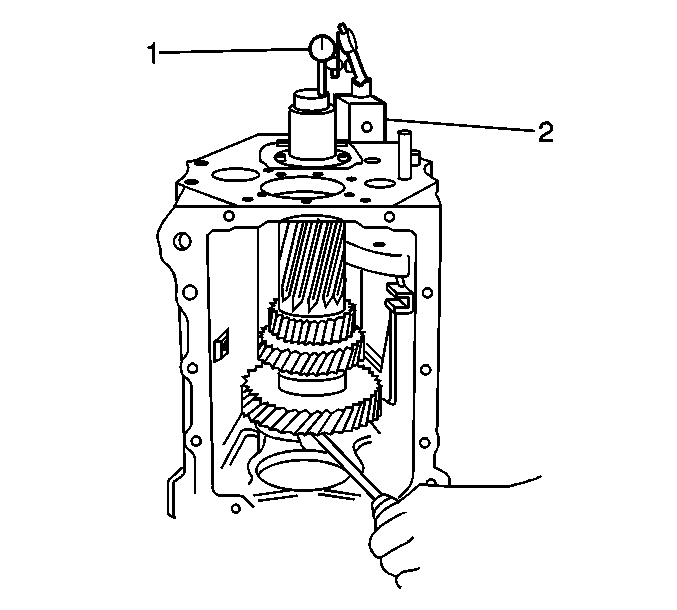
end play. Use the following procedure:
| 11.3. | Using a screwdriver, or the equivalent, lift the countershaft
and record the measurement. |
The countershaft end play should be 0.05-0.15 mm (0.002-0.006 in).
| 11.4. | Remove the countershaft rear bearing retainer and bolts. |
| 11.5. | Add shim(s) under the bearing retainer to achieve the correct
end play. |
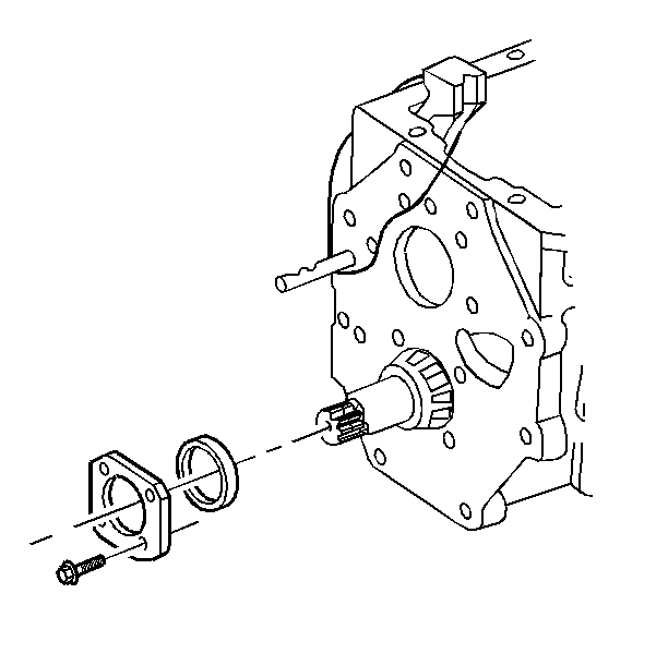
- Apply threadlocker GM P/N 12345493
to the countershaft retainer bolts.
- Install the countershaft bearing retainer and bolts.
Tighten
Tighten the countershaft bearing retainer bolts to 35 N·m
(26 lb ft).
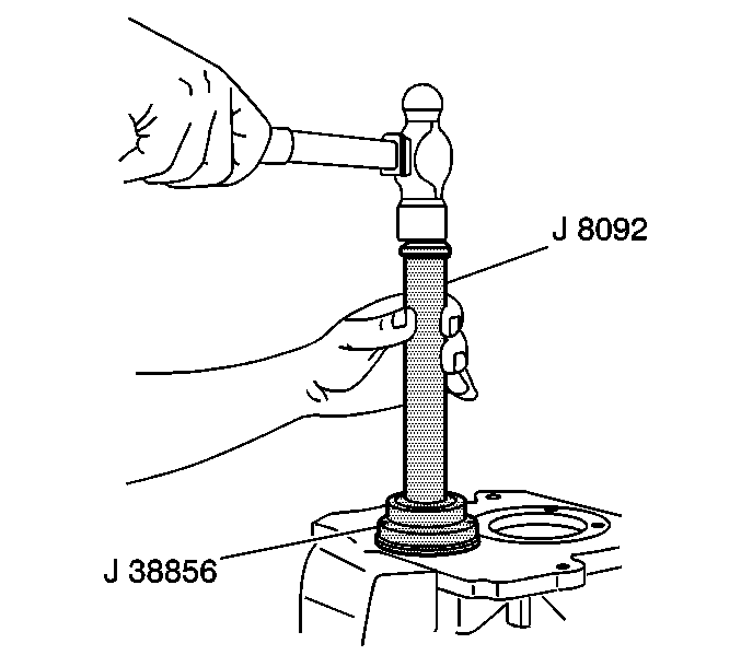
- Using the J 38856
with the J 8092
, install a NEW front countershaft bearing cap. When properly
installed, the outer lip of the cap will be flush with case.
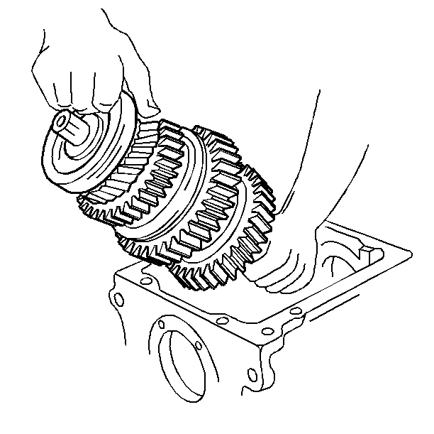
- Install the mainshaft
assembly into the transmission case.
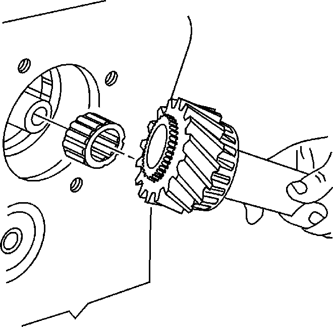
- Lubricate the main drive
gear bearing with transmission fluid.
- Install the main drive gear bearing and the input shaft into
the transmission case.
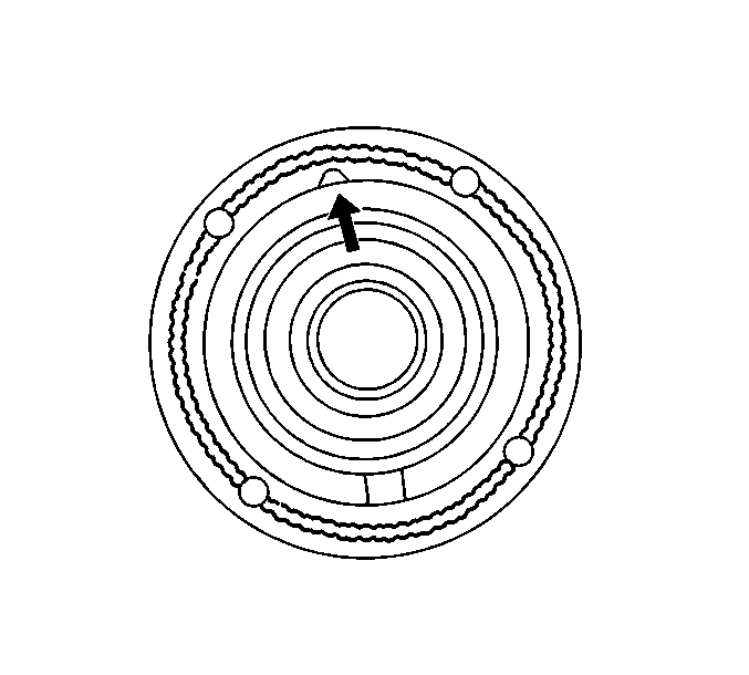
- Apply a thin layer of
RTV sealer GM P/N 12345739, or the equivalent, to the input
shaft retainer mating surface. Excessive amounts could plug the
bearing oil passage.
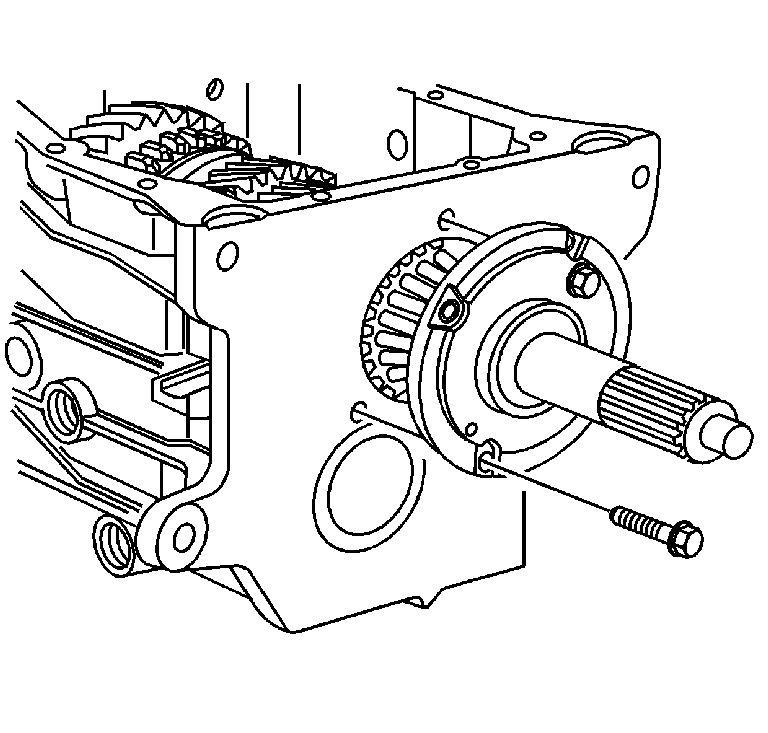
- Install the input shaft
retainer. Position the retainer with the oil hole at the top-center position.
- Apply threadlocker GM P/N 12345493 to the input
shaft retainer bolts.
- Install the input shaft retainer bolts.
Tighten
Tighten the input shaft retainer bolts to 22 N·m (16 lb ft).
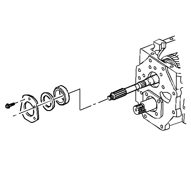
- Position the transmission
with the front of the case down.
- Install the mainshaft rear bearing cup.
- Temporarily install the mainshaft rear bearing retainer and bolts.
Tighten
Tighten the mainshaft rear bearing retainer bolts finger tight only.
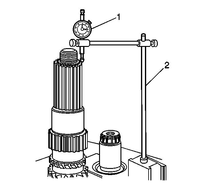
- Measure the countershaft
end play. Use the following procedure:
| 25.3. | Using a screwdriver, or the equivalent, lift the mainshaft and
record the measurement. |
The mainshaft end play should be 0.05-0.15 mm (0.002-0.006 in).
| 25.4. | Remove the mainshaft rear bearing retainer and bolts. |
| 25.5. | Add shim(s) under the bearing retainer to achieve the correct
end play. |

- Apply threadlocker GM P/N 12345493
to the mainshaft rear bearing retainer bolts.
- Install the mainshaft rear bearing retainer and bolts.
Tighten
Tighten the mainshaft rear bearing retainer bolts to 35 N·m
(26 lb ft).
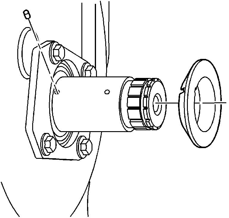
- Install the thrust washer
pin in the countershaft.
- Install the thrust washer. The tapered side faces toward the front
of the transmission.
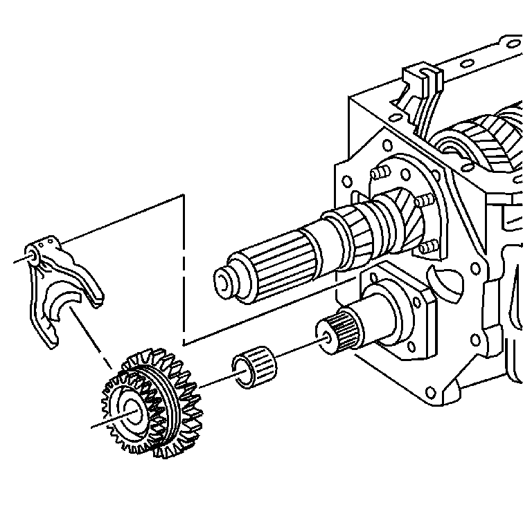
- Lubricate the overdrive
gear bearing with transmission fluid.
- Install the overdrive speed gear bearing.
- Install the overdrive speed gear assembly onto the overdrive
speed shift shaft and the countershaft. Slide the overdrive speed
gear fork and the overdrive speed gear assembly onto the shift
shaft.
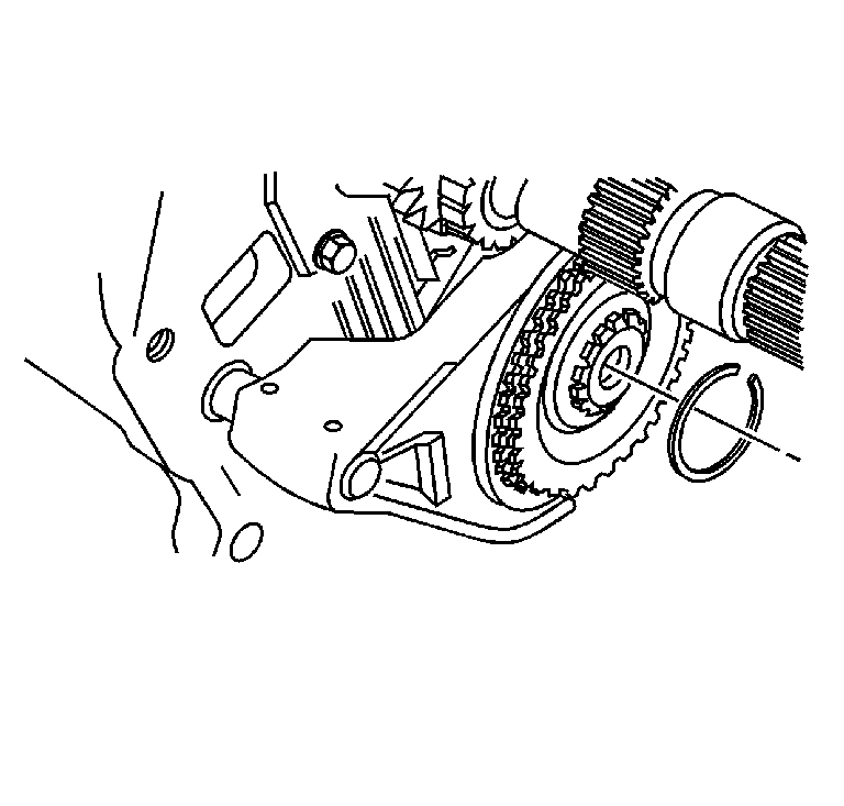
- Install the overdrive
speed gear clutch gear retainer ring.
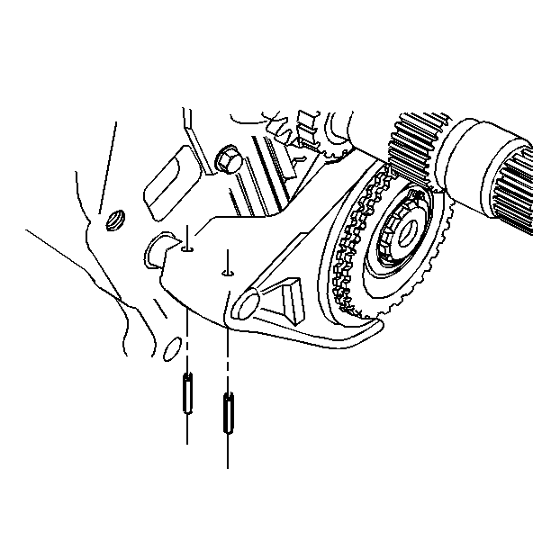
- Install the overdrive
speed gear shift fork roll pins. Support the fork, and drive the roll pins
downward from the top of the fork.
Caution: When handling parts that have been preheated for installation purposes,
always wear leather welding gloves with a minimum amount of handling time.
Failure to wear leather gloves may result in severe skin burns or personal
injury.
- Using the J 25070
,
or equivalent, heat the mainshaft overdrive gear, the vehicle speed sensor
reluctor wheel (RWD models), and the mainshaft spacer (HD 3500 models),
for fifteen minutes.
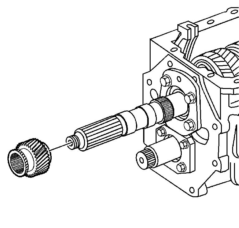
- Install the mainshaft overdrive gear on the mainshaft.
- Using the J 22828
, ensure the mainshaft overdrive gear is fully seated against the mainshaft
rear bearing.
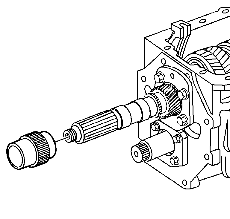
- (RWD models) Install the
vehicle speed sensor reluctor wheel on the mainshaft.
- Using the J 22828
, ensure the vehicle speed sensor reluctor wheel is fully seated against
the mainshaft overdrive gear.
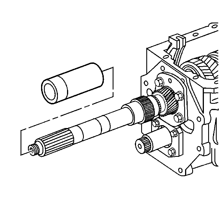
- (HD 3500 model)
Install the mainshaft spacer on the mainshaft.
- Using the J 22828
, ensure the mainshaft spacer is fully seated against the reluctor
wheel.
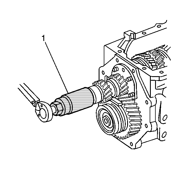
- Shift the transmission
into two gears, to lock the mainshaft.
- (4WD models) Using the J 38805
(1), install a NEW mainshaft washer and the nut.
Tighten
Tighten the mainshaft nut to 540 N·m (400 lb ft).
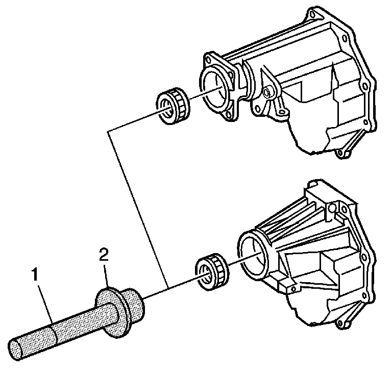
- (RWD models) Using J 38807
(2) and J 8092
(1),
install the rear output shaft rear bearing in the transmission extension.
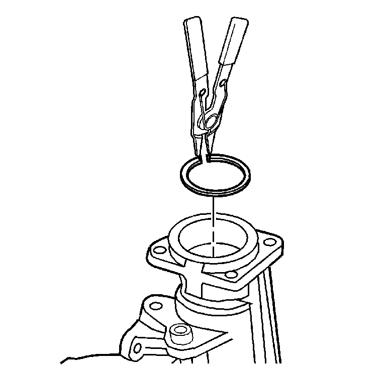
- (RWD models) Install the mainshaft
rear bearing retainer ring.
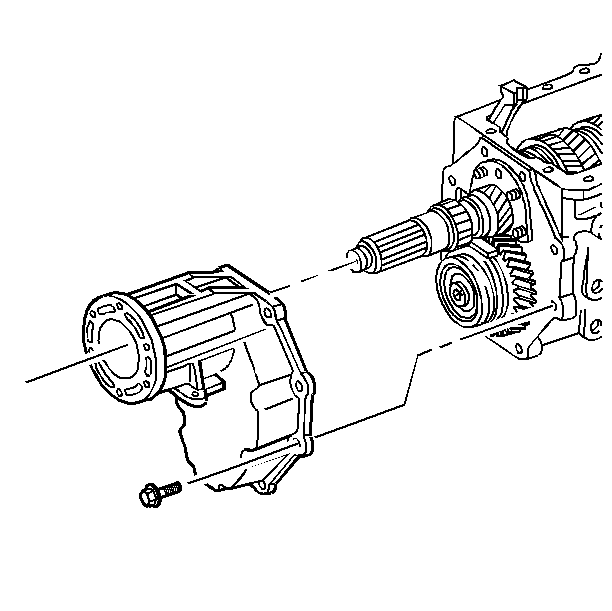
- Clean any oil from the
sealing surface of the transmission extension and the rear of the case.
- Apply RTV sealer GM P/N 12345739 on the mating surfaces
of the transmission extension.
- (4WD models) Install the transmission extension to the transmission
case.
Tighten
Tighten the bolts to 54 N·m (40 lb ft).
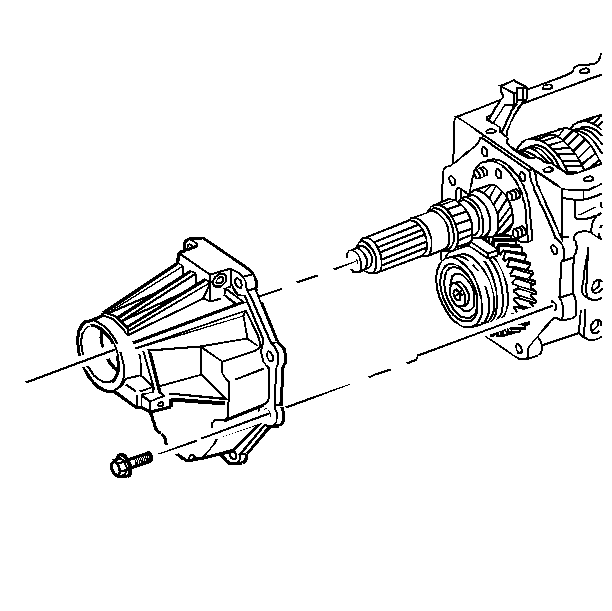
- (RWD models) Install the
transmission extension to the transmission case.
Tighten
Tighten the bolts to 54 N·m (40 lb ft).
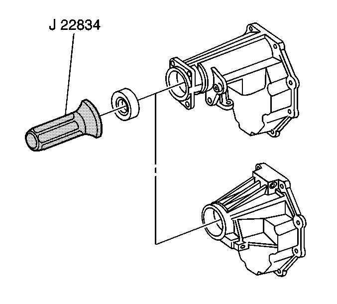
- (RWD models) Using the J 22834-A
, install a new mainshaft seal in the transmission
extension.
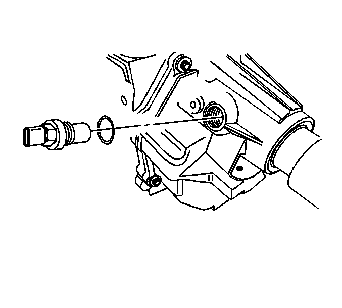
- (C 800 models)
Install the vehicle speed sensor (VSS). Lubricate the O-ring for ease
of installation.
Tighten
Tighten the VSS to 16 N·m (12 lb ft).
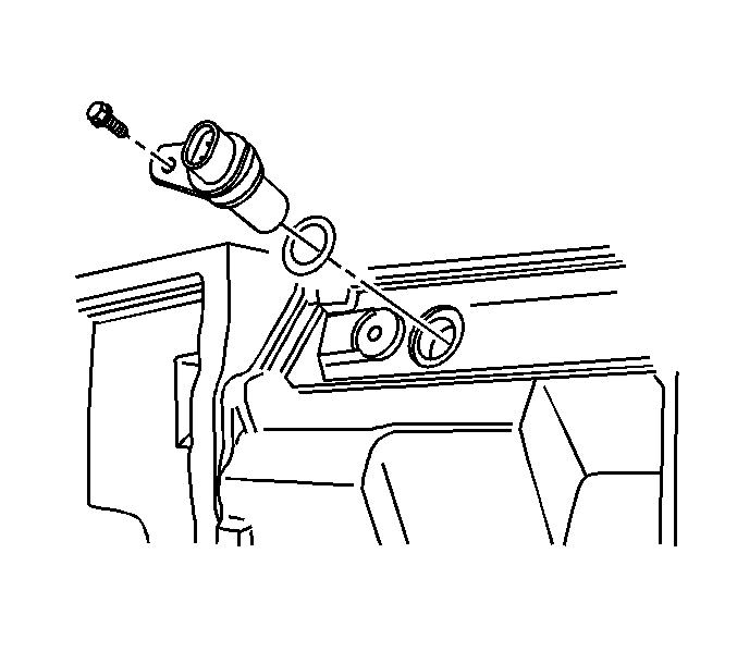
- (C 400 models)
Install the VSS. Lubricate the O-ring seal.
- Install the VSS bolt.
Tighten
Tighten the VSS bolt to 16 N·m (12 lb ft).
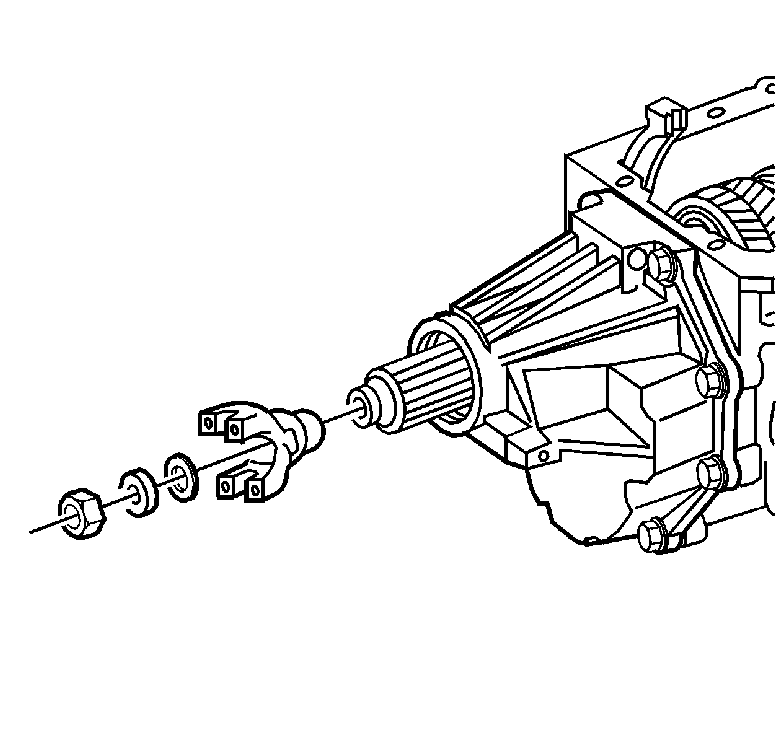
- (RWD models) Install the
yoke assembly .
- (RWD models) Install a NEW spline seal, a NEW washer, and the
nut.
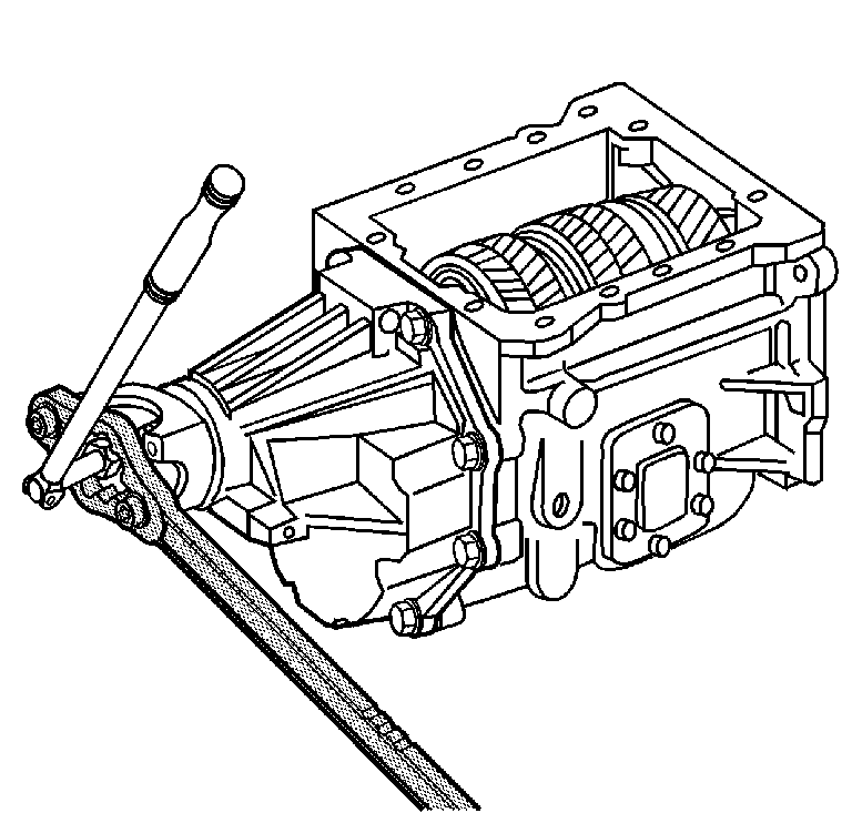
- Use the J 8614-01
to hold the propeller shaft yoke.
- Shift the transmission into 1st gear, to aid the tightening of
the yoke nut.
Tighten
Tighten the yoke nut to 441 N·m (325 lb ft).
- Fill the transmission to the proper level with Synthetic Manual
Transmission Fluid GM P/N 12346190.
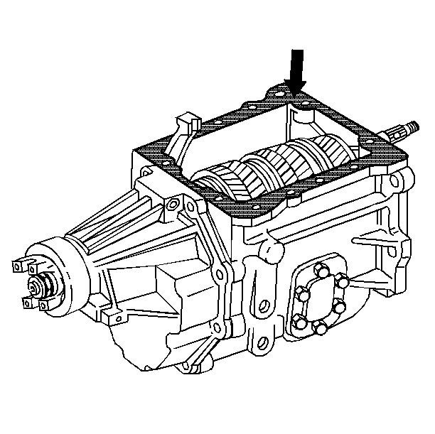
- Apply RTV sealer GM P/N 12345739,
or the equivalent, to the mating surfaces of the transmission cover.
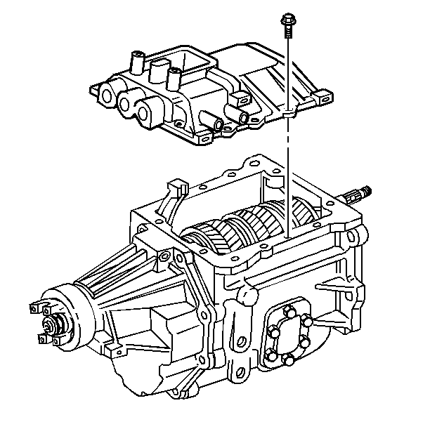
- Install the shift cover
to the transmission case.
- Install the shift cover bolts and the brackets to their original
location.
Tighten
Tighten the bolts to 27 N·m (20 lb ft).
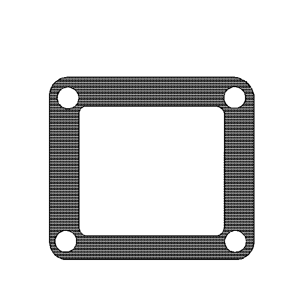
- Apply RTV sealer GM P/N 12345739,
or the equivalent, to the shift cover side of the shift tower spacer.
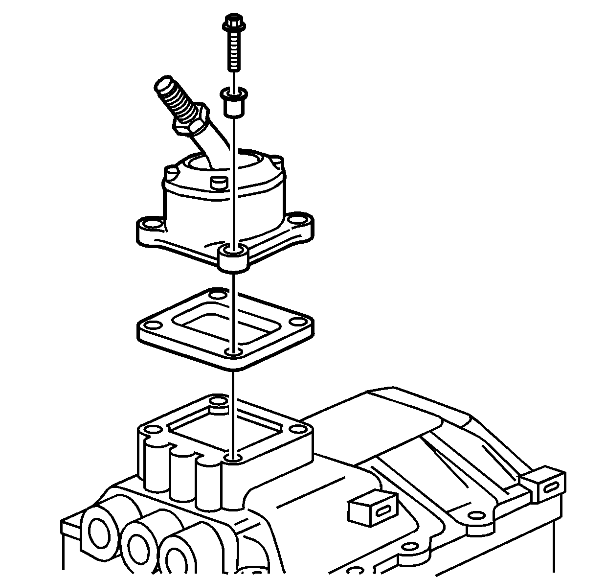
- Install the shift tower
spacer to the shift cover.
- Install the shift lever to the spacer.
- Install the shift lever bolts and bushings.
Tighten
Tighten the bolts to 11 N·m (97 lb in).


