Important:
| • | Only disassemble the synchronizer sleeve from the synchronizer
hub if there is a suspected gear shift concern. |
| • | For installation alignment, scribe an alignment mark on the synchronizer
hubs and synchronizer sleeves before disassembling. |
| • | Mark the synchronizers clutch gears and the blocking rings with
the corresponding gear, for correct diagnostic inspections. |
| • | Install the synchronizer components in the same location, if reusing. |
3rd/4th Speed Gear Synchronizer Disassembly
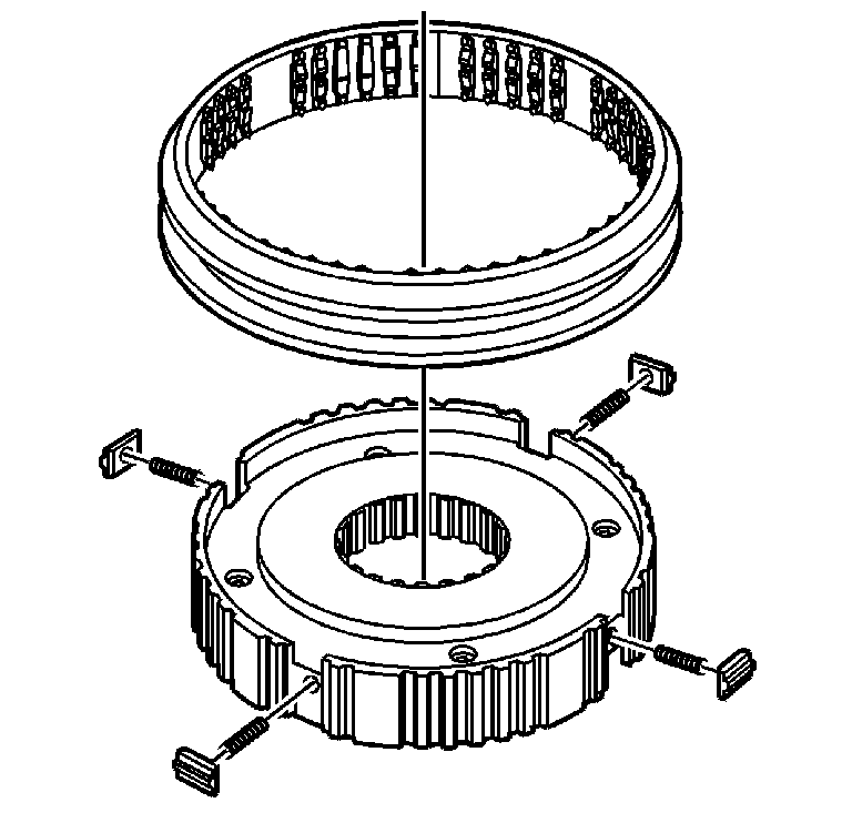
- Lay the synchronizer on
a shop towel, with the selector teeth down.
- Cover with the shop towel.
- Slide the synchronizer sleeve off the synchronizer hub.
- Remove the three springs and the three inserts.
5th (Overdrive) Speed Gear Synchronizer Disassembly
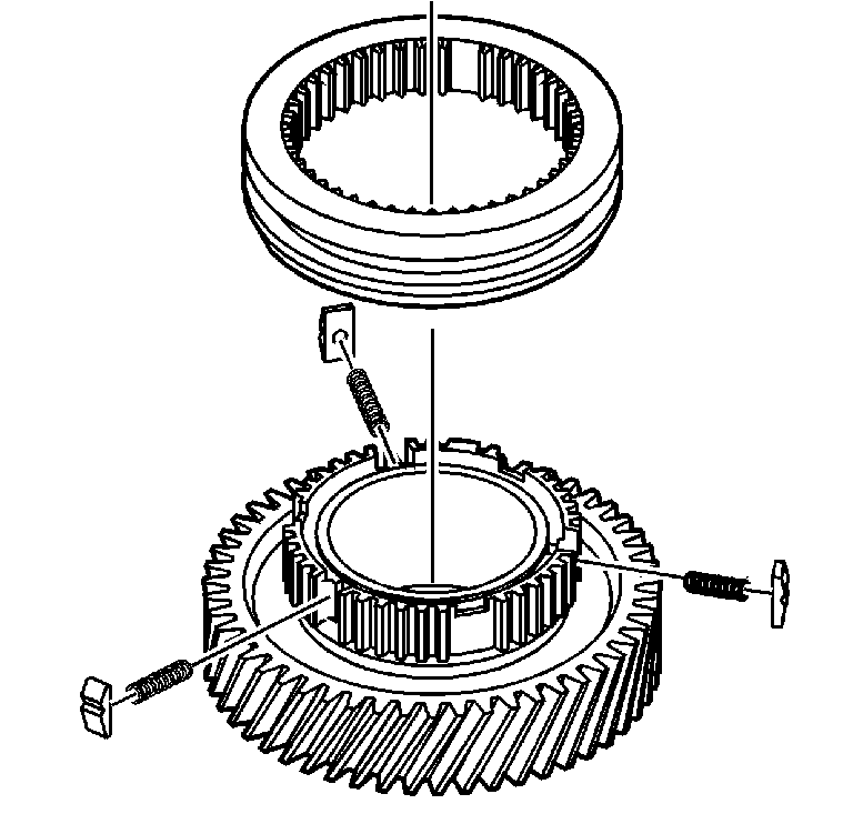
- Lay the 5th speed gear
assembly on a shop towel, with the gear side down.
- Cover with the shop towel.
- Slide the synchronizer sleeve off the synchronizer hub.
- Remove the three springs and the three inserts.
1st/2nd Speed Gear Synchronizer Disassembly
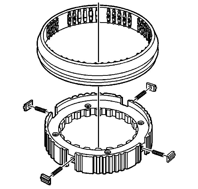
- Lay the 1st/2nd speed
gear assembly on a shop towel, with the 2nd speed gear side up. The tapered
side of the sleeve is the 2nd speed gear side.
- Cover with the shop towel.
- Slide the synchronizer sleeve off the synchronizer hub.
- Remove the four springs and the four inserts.
Reverse Speed Gear Synchronizer Disassembly
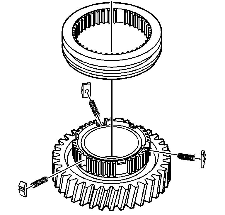
- Lay the reverse speed
gear assembly on a shop towel, with the reverse gear down.
- Cover with the shop towel.
- Slide the synchronizer sleeve off the synchronizer hub.
- Remove the three springs and the three inserts.
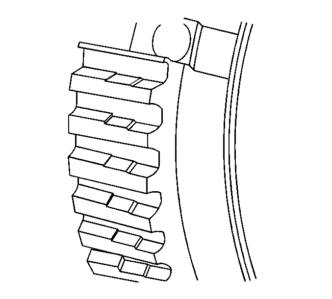
- Clean all the parts in
a suitable cleaning solvent. Air dry all the parts.
- Inspect the synchronizer sleeves for a sliding fit on the synchronizer
hubs.
- Replace the 3rd and 4th gear synchronizer hub that does not require
a force fit on the mainshaft splines.
- Inspect the synchronizer hub for wear on the external splines.
A stepped effect on the teeth, due to wear, may cause shift conditions.
- Inspect the 3rd and 4th gear synchronizer hub for a force fit
on the mainshaft splines.
- Replace a worn hub.
- Correct the cause such as, but not limited to, the following:
| • | Engine related vibrations |
| • | Driving at a low speed in a high gear |
| • | Defective vibration damper or crankshaft |
| • | Incorrectly set injector pump |
- Inspect the inserts and springs for wear or damage.
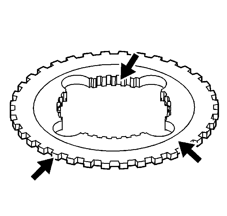
- Inspect the mainshaft
drive gear clutch gear teeth for wear.
- Inspect the input shaft clutch gear teeth for wear.
- Inspect the clutch gear for 4th gear, reverse gear, and overdrive
gear wear.
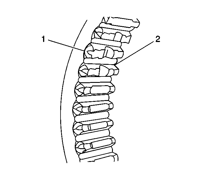
- Inspect the synchronizer
sleeve teeth (1) for the following, which may cause shift conditions:
- Inspect the synchronizer sleeve detent stops (2) for wear
or for being chipped off.
- Replace the synchronizer assembly if the teeth or stops show the
above conditions.
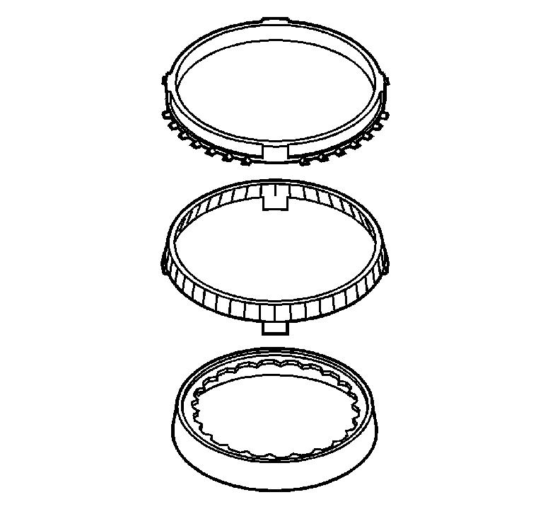
- Inspect the three-piece
1st/2nd synchronizer blocker rings for wear.
- Replace the blocker ring assembly if the middle ring grooves
are worn away.
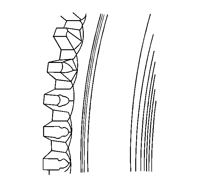
- Inspect all of the synchronizer
blocker rings for worn shift teeth.
- Inspect the blocker rings for worn friction material.
- Replace the synchronizer ring assembly if any of the above conditions
are present.
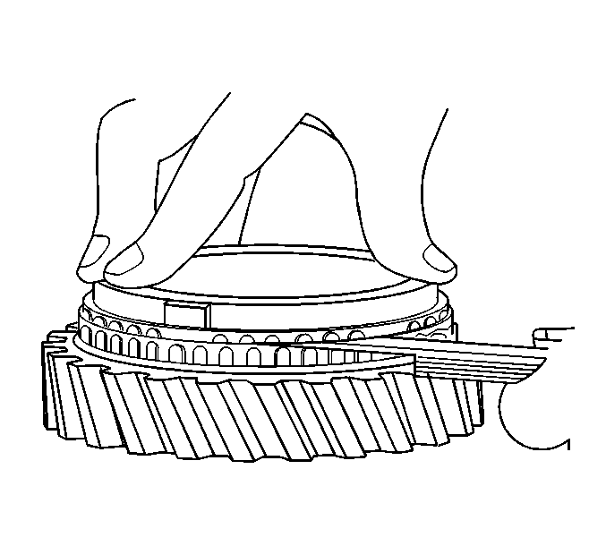
- Measure the cap between
the verical faces of the blocking ring teeth and the synchronizer clutch gear
as follows:
| 20.1. | Assemble the correct blocker ring to the correct gear. |
| 20.2. | Apply pressure to the blocker ring to fully seat the ring. |
| 20.3. | Using a feeler gauge, measure between the blocker ring teeth and
the teeth on the gear. |
| • | 1st gear, between the hub and outer ring, 1.37-0.31 mm (0.054-0.012
in) |
| • | 2nd gear 2.16-1.14 mm (0.085-0.045 in) |
| • | 3rd gear 1.73-0.76 mm (0.068-0.030 in) |
| • | 4th gear 2.10-1.19 mm (0.079-0.047 in) |
| • | Overdrive gear 1.83-1.07 mm (0.072-0.042 in) |
| • | Reverse gear 2.24-1.47 mm (0.088-0.058 in) |
- If a NEW blocker ring is used, and the standard clearance cannot
be obtained, replace the gear.
3rd/4th Speed Gear Synchronizer Assembly

- Lay the synchronizer hub
on the 3rd speed gear synchronizer blocking ring and clutch gear. The ring
and gear will hold the hub up.
- Slide the synchronizer sleeve on the synchronizer hub.
| • | Align the large tooth with the large slot in the sleeve. |
| • | The sleeve can go either direction, if it is not marked. |
- Using a small screwdriver, install the three springs and the three
inserts.
- Move the sleeve to the neutral position, to hold the springs and
inserts in position.
5th (Overdrive) Speed Gear Synchronizer Assembly

- Lay the 5th speed gear
assembly, with the gear side down, on the workbench.
- Slide the synchronizer sleeve on the synchronizer hub, with the
tapered side of the sleeve towards the gear.
- Using a small screwdriver, install the three springs and the three
inserts.
- Move the sleeve to the neutral position, to hold the springs and
inserts in position.
1st/2nd Speed Gear Synchronizer Assembly

- Lay the 1st/2nd speed
gear assembly on the 1st speed gear synchronizer inner and middle rings. The
rings will hold the hub up.
- Slide the synchronizer sleeve on the synchronizer hub.
| • | Align the sleeve to the hub. |
| • | The sleeve will fit in only one direction on the hub. |
| • | The tapered side of the sleeve faces up, or toward second gear. |
- Using a small screwdriver, install the four springs and the four
inserts.
- Move the sleeve to the neutral position, to hold the springs and
inserts in position.
Reverse Speed Gear Synchronizer Assembly

- Lay the reverse speed
gear assembly, with the reverse gear down, on the workbench.
- Slide the synchronizer sleeve on the synchronizer hub.
| • | Align the sleeve to the hub. |
| • | The sleeve will fit in only one direction on the hub. |
| • | The tapered side of the sleeve faces toward reverse gear. |
- Using a small screwdriver, install the three springs and the three
inserts.
- Move the sleeve to the neutral position, to hold the springs and
inserts in position.


