
| Subject: | Fuel Leaks (Inside of Engine) and Fuel Leaks (Outside
of Engine) Diagnostics |
| Models: | 2001 Chevrolet and GMC C/K Pickup Models (Silverado, Sierra) |
| with 6.6L Engine (VIN 1 -- RPO LB7) |
This bulletin is being issued to add the Fuel Leaks (Inside of Engine)
and Fuel Leaks (Outside of Engine) diagnostics in the Engine Controls-6.6L
sub-section of the Service Manual.
The following information has been updated within SI. If you are using
a paper version of this Service Manual, please make a reference to this bulletin
on the affected page.
Fuel Leaks (Inside of Engine)
Important: If you were directed here from Fuel Return System Diagnosis, go to step 15.
This will be performed with the same components disconnected as stated in
that test.
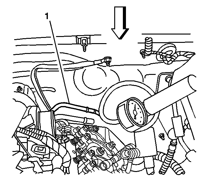
- Disconnect the fuel return line (1)
at the engine. Refer to Quick Connect Fittings Service (Metal Collar).
- Remove the air duct from the air cleaner assembly to the turbo
inlet.
- Remove the air intake pipe. Refer to Air Intake Pipe Replacement.
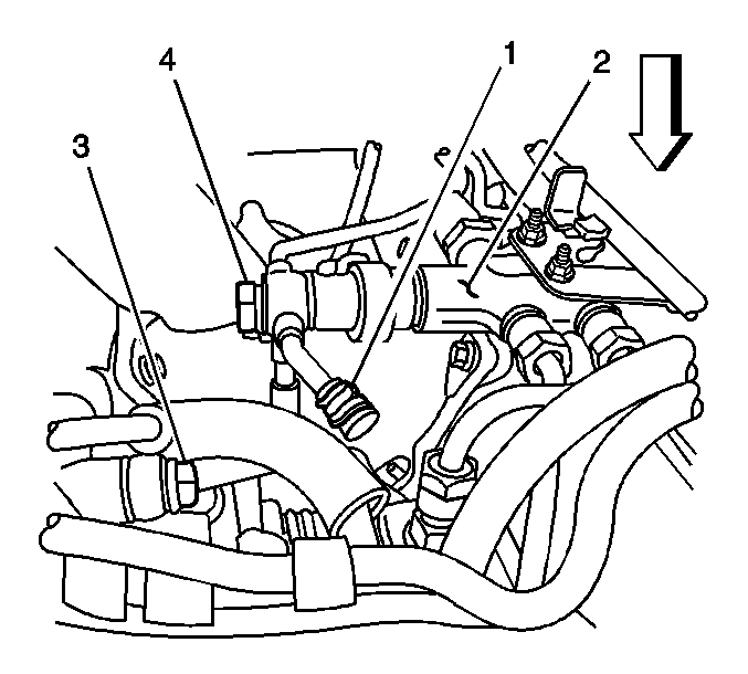
- Remove the fuel return rubber hose of
the fuel injection pump from the junction block (2). Cap the fitting
on the block with a 9.53 mm (3/8 in) rubber cap (1)
to prevent fuel leakage.
- Install the J 23738-A Vacuum Pump at the fuel return
pipe.
- Apply 50.8 kPa (15 inches Hg) of vacuum to
the pipe.
| • | If the vacuum holds, go to step 23. |
| • | If the vacuum does not hold, go to step 7. |
- Remove the generator. Refer to Generator Replacement in Engine
Electrical.
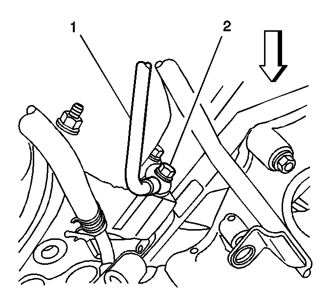
- Disconnect the fuel return line (1)
from the right front cylinder head and left rear cylinder heads.
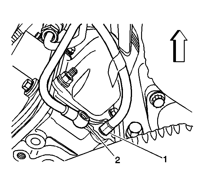
- Install the black hose (1) from the J 45873
on to each cylinder head return port and install the J 23738-A
onto the black hose on the right cylinder head.
- Apply 50.8 kPa (15 inches Hg) of vacuum to
the port.
- Install the J 23738-A to the black hose on the left
cylinder head return port and apply 50.8 kPa (15 inches Hg)
of vacuum.
| • | If the vacuum holds on both sides, replace the fuel return line
between the cylinder head return ports. |
| • | If the vacuum does not hold on one or both sides, go to step 12. |
- Perform the lower valve cover removal procedure for the bank(s)
that did not hold vacuum. Refer to Valve Rocker Arm Cover Replacement-Lower
Right and Valve Rocker Arm Cover Replacement-Lower Left in Engine Mechanical.
Then go to step 13.
- Connect the fuel return line to both cylinder heads.
Tighten
Tighten the bolts to 15 N·m(11 lb.ft).
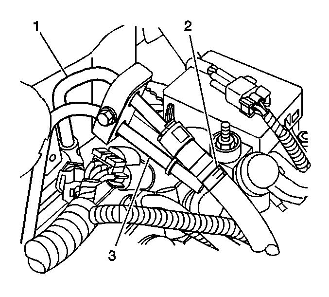
- Install the J 42964-1 9.53 mm
(3/8 in) Fuel Pipe Shutoff Valve (2) to the fuel return line (1).
- Install the J 35800-A Fuel Injector Cleaner on the
J 42964-1 3/8 Fuel Pipe Shutoff Valve port closest to the fuel
return line.
- Ensure that the shutoff valve is closed.
- Add 0.296L (10 ounces) of diesel fuel and 0.118L (4 ounces)
of oil dye to the J 35800-A Fuel Injector Cleaner.
- Connect the shop air supply to the J 35800-A.
- Adjust the pressure regulator on the J 35800-A to
103 kPa (15 psi).
- Clean the fuel injectors and fuel return lines with brake cleaning
solvent and let dry.
- Open the valve on the bottom of the J-35800-A fuel injector
cleaner canister.
- Inspect for leaks around the fuel injectors and the spill lines
with a J 28428-E High Intensity Black Light Kit. Then go to step 29.
- Remove both upper valve covers. Refer to Valve Rocker Arm Cover
Replacement-Upper Left and Valve Rocker Arm Cover Replacement-Upper Right
in Engine Mechanical.
- Install the fuel injector feed pipes.
Tighten
Tighten the fuel feed pipes to 44 N·m (32 lb.ft.).
- Add 0.237L (8 ounces) of oil dye to the fuel tank. On dual
tank systems, add the dye to the front, or primary, tank. Refer to Fuel System
Description.
- Start the engine.
- Increase the fuel pressure to 160 MPa with a scan tool.
- Inspect for leaks around the fuel injectors with a J 28428-E
High Intensity Black Light Kit. Then go to step 29.
- Tighten or replace any leaking components or gaskets.
- Perform the lower valve cover installation procedures as necessary.
Refer to Valve Rocker Arm Cover Replacement-Lower Left and Valve Rocker Arm
Cover Replacement-Lower Right in Engine Mechanical .
Fuel Leaks (Outside of Engine)
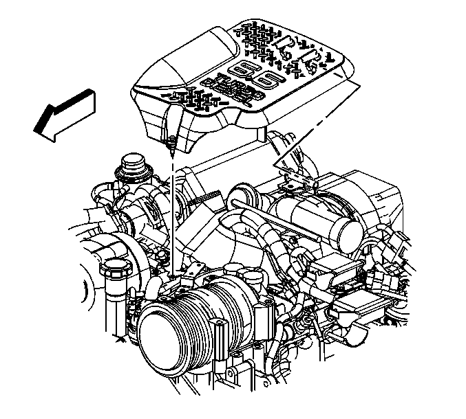
- Remove the upper intake manifold sight
shield using the following procedure:
| 1.1. | Remove the retaining bolt in the front of the shield. |
| 1.2. | Lift up on the front of the shield. |
| 1.3. | Lift the shield off the rear bracket. |
- Clean all of the fuel lines between the fuel injection pump and
the fuel injectors using brake cleaning solvent, and let dry.
- Add 0.237L (8 ounces) of oil dye to the fuel tank. On dual
tanks, add the dye to the front, or primary, tank. Refer to Fuel System Description.
- Connect a scan tool to the DLC.
- Start and idle the engine for 3-5 minutes.
- Command the fuel pressure control to 160 MPa (23,206 psi)
with a scan tool.
- Inspect for fuel leaks around the fuel injection pump, junction
block, fuel rails, and fuel injector supply lines with a J 28428-E
High Intensity Black Light Kit.
Tighten or replace any leaking
lines or components. Refer to the following:
| • | Fuel Injection Line Routing Diagram |
| • | Fastener Tightening Specifications |
| • | Fuel Rail Assembly Replacement-Bank 1 |
| • | Fuel Rail Assembly Replacement-Bank 2 |
| • | Fuel Junction Block Replacement |
| • | Fuel Injection Pump Replacement |


