Side Assist Step Pad Warping (Install New Step Pad Kit)

| Subject: | Side Assist Step Pad Warping (Install New Step Pad Kit) |
| Models: | 2001 GMC Sierra C3 Luxury Pickup Models |
| With Uplevel Side Assist Steps (RPO BVF) |
Condition
Some customers may comment that the step pad(s) attached to the side assist (runningboard) steps is warping.
Correction
A new side assist step pad kit, P/N 88979974 which integrates two new fastening points to each pad, has been developed to correct this condition. Install this step pad kit on the affected vehicles using the following procedure and the parts listed below. The kit contains driver and passenger side step pads. The new step pads should be installed on BOTH assist steps.
Tools Required
| • | Standard Power Drill |
| • | 11 mm (0.433 in) (3/8 in) Socket |
| • | 16 mm (0.625 in) (5/8 in) Drill Bit |
| • | 3 mm (0.125 in) (1/8 in) Drill Bit |
| • | Center Punch |
| • | Masking Tape |
| • | Round File |
- Raise the vehicle. Refer to Lifting and Jacking the Vehicle in the General Information sub-section of the Service Information.
- Clean the underside of the assist step support.
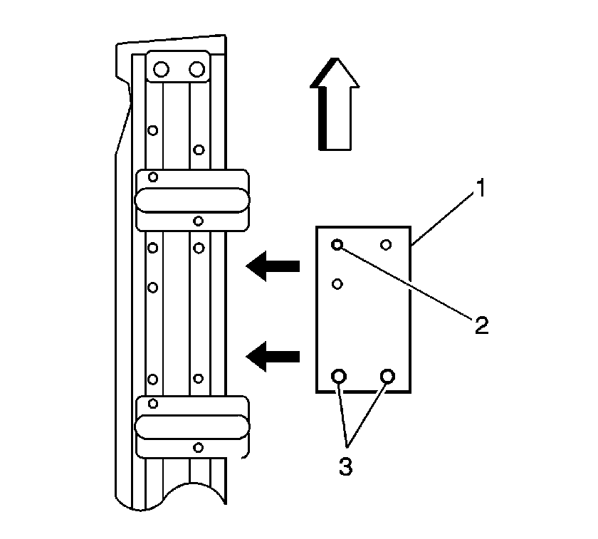
- Using the template (1) provided, locate the three 6 mm (0.24 in) holes in the template (2) over the three thread forming nuts on the driver's side assist step support near the rear of the front door. Ensure that the forward mark on the template is facing the front of the vehicle.
- Tape the template to the underside of the assist step support. Refer to the illustration.
- Center punch the two centers on the template. Carefully remove the template.
- Install the template on the passenger side following steps 3, 4 and 5.
- Drill 3 mm (0.125 in) (1/8 in) pilot holes into both assist step supports at the center punch marks through the supports, the cover and the existing step pads. Enlarge each hole with the 16 mm (0.625 in) (5/8 in) drill bit.
- Remove the existing nuts and the old step pad(s).
- Using a file, remove any burrs on the underside of the supports.
- Apply anti-corrosion material to the exposed metal using the information found in the applicable Service Manual and GM Refinish Material Booklet 4901M-D-2002 (English) or 4901M-D-F2002 (French).
- Place the new step pads in their proper location as identified on the underside of the pads.
- Using the hex nuts saved from the removal of the original step pad, and the four nuts supplied with the kit, install a nut on each post using the 11 mm (0.433 in) (3/8 in) drive socket with a hand ratchet.

Important:
• Verify that all of the parts are included in the kit. • Two new 16 mm (0.625 in) (5/8 in) diameter holes (3)
will need to be drilled on each side assist step support step plate.
Important: Tighten the nuts leaving 0.46 mm (0.018 in) clearance between the nut and the step plate. Use the 0.46 mm (0.018 in) feeler gauge provided.
Parts Information
Part Number | Description | Qty |
|---|---|---|
88979974 | Kit, Assist Step Pad | 1 |
The kit includes the following components: | ||
15169873 | Step Pad, Driver Side Cab | 1 |
15169872 | Step Pad, Passenger Side Cab | 1 |
-- | Nut, Hex | 4 |
-- | 0.018" Feeler Gauge | 1 |
-- | Template | 1 |
-- | Instruction Sheet | 1 |
Parts are expected to be available 8-15-2002 from GMSPO.
Warranty Information
For vehicles repaired under warranty, use:
Labor Operation | Description | Labor Time |
|---|---|---|
B9705 | Pad, Assist Step - Replace (BOTH) | 0.8 hr |
