Fuel Hose/Pipes Replacement - Chassis Pickup
Tools Required
J 44581 Fuel Line Disconnect Tool
Removal Procedure
- Disconnect the chassis fuel pipes from the engine fuel pipes. Refer to Metal Collar Quick Connect Fitting Service .
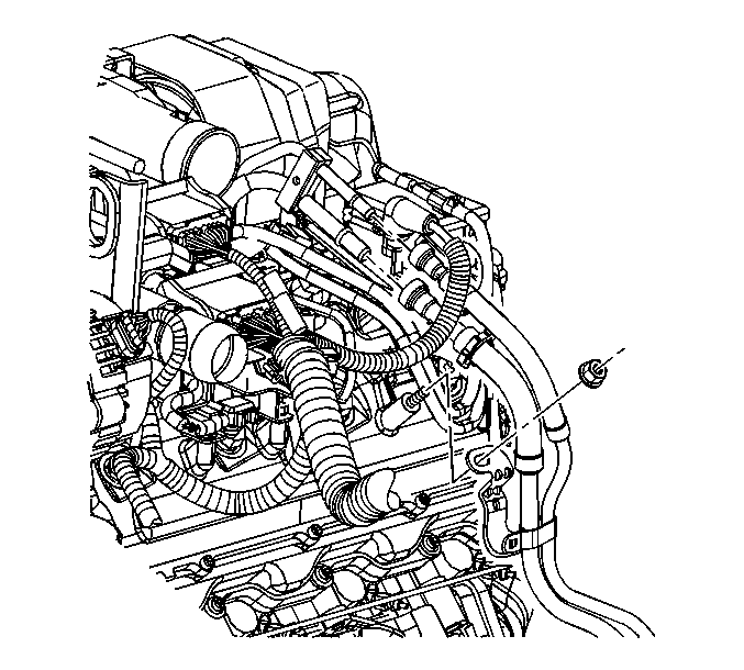
- Remove the retaining nut from the fuel bundle bracket.
- Raise the vehicle. Refer to Lifting and Jacking the Vehicle in General Information.
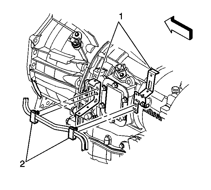
- Remove the fuel bundle clips (2) from the transmission brackets (1).
- Disconnect the chassis harness from the retaining clips.
- Remove the fuel system cooler (1) if necessary. Refer to Fuel Cooler Replacement .
- Disconnect the chassis fuel pipes (1, 2) from the fuel tank fuel pipes.
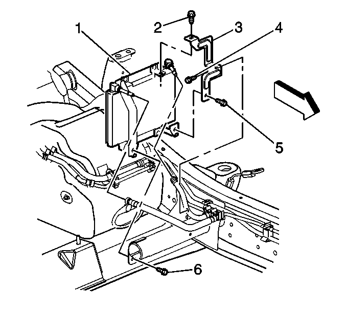
- Remove the fuel bundle retaining nuts (1) from the chassis.
- Disconnect the electronic brake control module mounting bracket (3) from the frame rail (5).
- Allow the electronic brake control module to remain loose in order to allow fuel pipe clearance.
- Remove the fuel bundle using the following procedure:
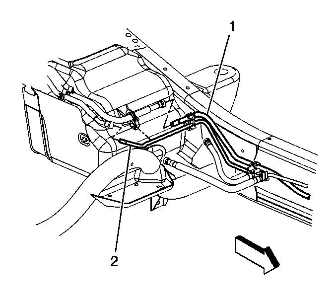
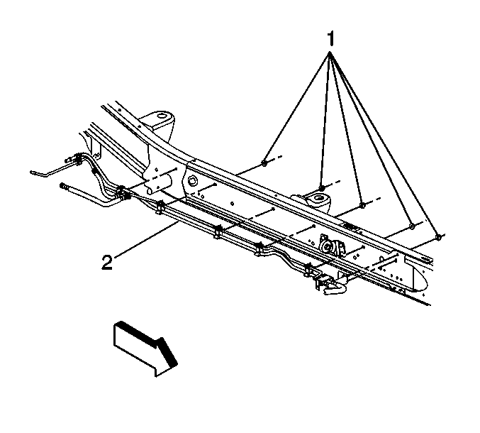
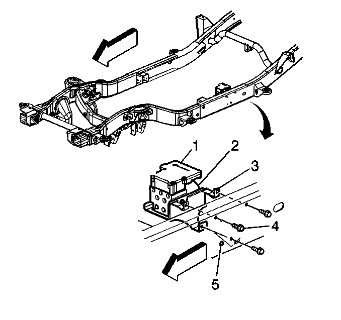
| 11.1. | Guide the fuel bundle (2) pipes towards the rear of vehicle to clear the engine. |
| 11.2. | Lower the fuel bundle while moving it foreword and out. |
Installation Procedure
- Install the fuel pipe bundle using the following procedure:
- Attach the fuel bundle to the chassis.
- Install the fuel system cooler (1). Refer to Fuel Cooler Replacement .
- Connect the fuel bundle clips (2) to the transmission brackets (1).
- Install the electronic brake control module mounting bracket (3) to the frame rail (5).
- Lower the vehicle.
- Install the fuel bundle bracket.
- Connect the chassis fuel pipes to the engine fuel pipes. Refer to Metal Collar Quick Connect Fitting Service .
- Purge air from the fuel system. Refer to Fuel Feed Pipe and Return Pipe Purging .

| 1.1. | Install the fuel bundle (3) to the chassis by guiding the pipes towards the rear of vehicle. |
| 1.2. | Lift the fuel pipes, while guiding the forward portion of the pipes up towards the engine connections. |
Notice: Use the correct fastener in the correct location. Replacement fasteners must be the correct part number for that application. Fasteners requiring replacement or fasteners requiring the use of thread locking compound or sealant are identified in the service procedure. Do not use paints, lubricants, or corrosion inhibitors on fasteners or fastener joint surfaces unless specified. These coatings affect fastener torque and joint clamping force and may damage the fastener. Use the correct tightening sequence and specifications when installing fasteners in order to avoid damage to parts and systems.
Tighten
Tighten the fuel bundle retaining nuts (1) to 16 N·m (12 lb ft).


Tighten
Tighten the retaining bolts (4) to 25 N·m (18 lb ft).

Tighten
Tighten the bundle bracket retaining nut to 16 N·m (12 lb ft).
Fuel Hose/Pipes Replacement - Chassis Cab/Chassis
Removal Procedure
- Disconnect the chassis fuel pipes from the engine fuel pipes. Refer to Metal Collar Quick Connect Fitting Service .
- Remove the retaining nut from the fuel bundle bracket.
- Remove the fuel tank. Refer to Fuel Tank Replacement .
- Remove the fuel bundle clips (2) from the transmission brackets (1).
- Disconnect the chassis harness from the retaining clips.
- Remove the fuel system cooler. Refer to Fuel Cooler Replacement .
- Cap off the fuel pipes to prevent contamination.
- Remove the fuel bundle retaining nuts (2) from the chassis (1).
- Disconnect the electronic brake control module mounting bracket (3) from the frame rail (5).
- Allow the electronic brake control module to remain loose in order to allow fuel pipe clearance.
- Remove the fuel bundle (3) using the following procedure:
- If replacing an individual fuel pipe, remove the pipe from the retaining clips.


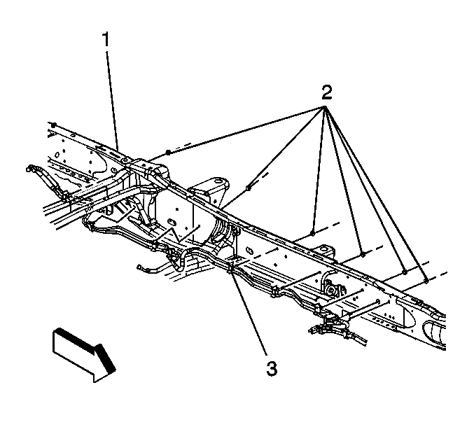

| 11.1. | Guide the fuel bundle (2) pipes towards the rear of vehicle to clear the engine. |
| 11.2. | Lower the fuel bundle while moving it foreword and out. |
Notice: Do not attempt to straighten any kinked nylon fuel lines. Replace any kinked nylon fuel feed or return pipes in order to prevent damage to the vehicle.
Installation Procedure
- If replacing an individual fuel pipe, place the new fuel pipe in the retaining clips.
- Install the fuel bundle (3) to the chassis (1) using the following procedure:
- Attach the fuel bundle to the chassis.
- Remove the fuel caps.
- Install the system cooler. Refer to Fuel Cooler Replacement .
- Connect the fuel bundle clips (2) to the transmission brackets (1).
- Install the fuel tank. Refer to Fuel Tank Replacement .
- Install the electronic brake control module mounting bracket (3) to the frame rail (5).
- Lower the vehicle.
- Install the fuel bundle bracket.
- Connect the chassis fuel pipes to the engine fuel pipes. Refer to Metal Collar Quick Connect Fitting Service .
- Purge air from the fuel system. Refer to Fuel Feed Pipe and Return Pipe Purging .

| 2.1. | Install the fuel bundle (3) to the chassis by guiding the pipes towards the rear of vehicle. |
| 2.2. | Lift the fuel pipes, while guiding the forward portion of the pipes up towards the engine connections. |
Notice: Use the correct fastener in the correct location. Replacement fasteners must be the correct part number for that application. Fasteners requiring replacement or fasteners requiring the use of thread locking compound or sealant are identified in the service procedure. Do not use paints, lubricants, or corrosion inhibitors on fasteners or fastener joint surfaces unless specified. These coatings affect fastener torque and joint clamping force and may damage the fastener. Use the correct tightening sequence and specifications when installing fasteners in order to avoid damage to parts and systems.
Tighten
Tighten the fuel bundle retaining nuts (1) to 16 N·m (12 lb ft).


Tighten
Tighten the EBCM bracket retaining bolts (4) to 25 N·m
(18 lb ft).

Tighten
Tighten the fuel bundle bracket retaining nut to 16 N·m
(12 lb ft).
Fuel Hose/Pipes Replacement - Chassis Cab/Chassis - Balance
Removal Procedure
- Remove the front fuel tank (5). Refer to Fuel Tank Replacement .
- Remove the auxiliary fuel tank (2). Refer to Fuel Tank Replacement .
- Remove the fuel pipes (2) using the following procedure:
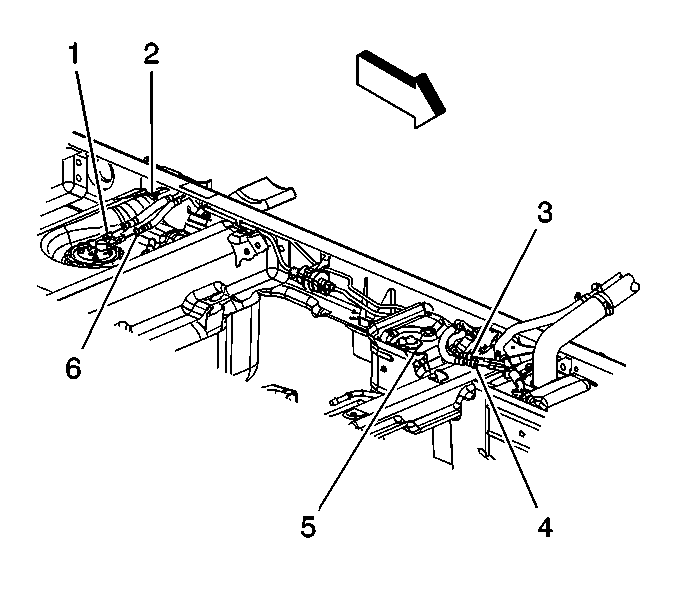
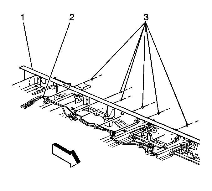
Notice: Do not attempt to straighten any kinked nylon fuel lines. Replace any kinked nylon fuel feed or return pipes in order to prevent damage to the vehicle.
| • | For the return pipe, remove the fuel pipe from the retaining clips. |
| • | For a balance pump fuel line, disconnect the fuel pipe from the balance pump and the retaining clips. |
Installation Procedure
- Install the fuel pipes (2) using the following procedure:
- Install the auxiliary fuel tank (2). Refer to Fuel Tank Replacement .
- Install the front fuel tank. Refer to Fuel Tank Replacement .

Notice: Do not attempt to straighten any kinked nylon fuel lines. Replace any kinked nylon fuel feed or return pipes in order to prevent damage to the vehicle.
| • | For the return pipe, install the fuel pipe to the retaining clips. |
| • | For a balance pump fuel line, connect the fuel pipe to the balance pump and the retaining clips. |

