Removal Procedure
- Remove the engine front cover. Refer to Engine Front Cover Replacement .
- Remove the upper oil pan. Refer to Upper Oil Pan Replacement .
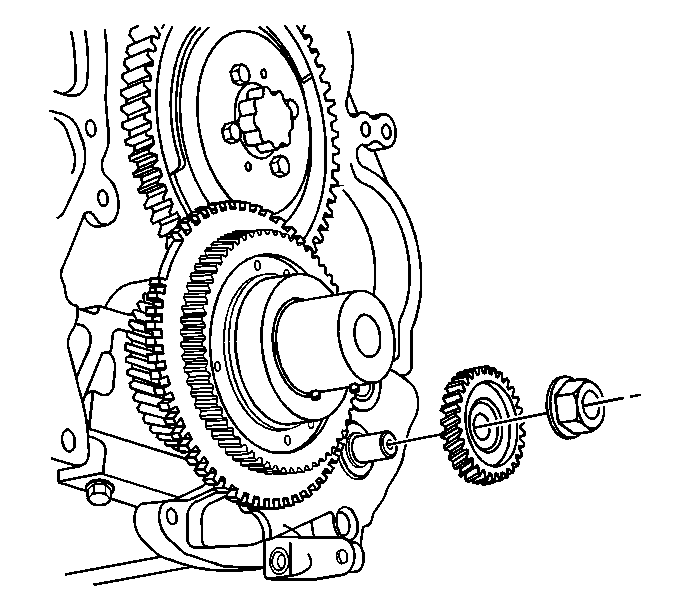
- While holding the secondary oil pump shaft with a hex driver, remove the oil pump driven gear nut.
- Remove the oil pump driven gear.
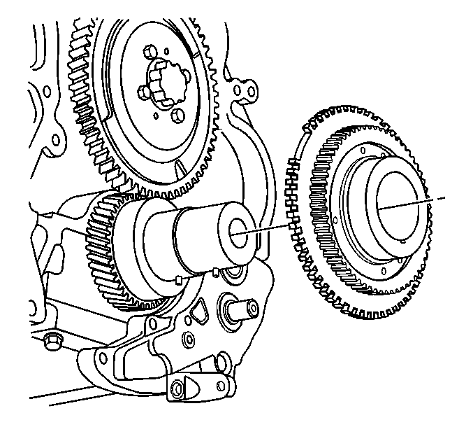
- Remove the oil pump drive gear and crankshaft sensor reluctor assembly. Do not damage the crankshaft reluctor teeth.
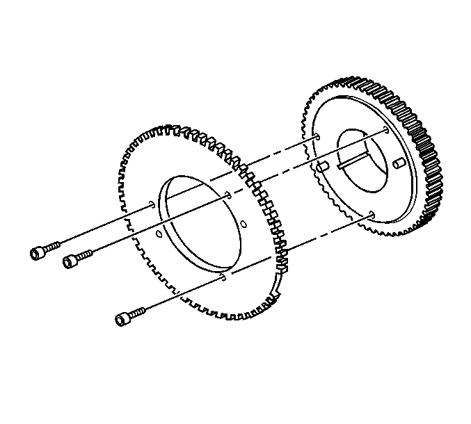
- Remove the bolts retaining the crankshaft reluctor to oil pump drive gear.
- Inspect the crankshaft reluctor for damaged or bent teeth.
- Inspect the crankshaft reluctor for being bent or warped.
- Inspect the oil pump drive gear for damaged or worn teeth.
- Inspect the oil pump drive gear crankshaft pin for wear.
- Inspect the groove for the crankshaft pin in the oil pump drive gear for wear.
- Replace any parts that are damaged or worn.

Notice: Do not use an impact driver to remove or install the oil pump driven gear nut. Use of an impact driver may shear the oil pump drive gear pin in the crankshaft.


Important: Do not remove the crankshaft reluctor from the oil pump drive gear unless replacing the crankshaft reluctor or the oil pump drive gear. The crankshaft reluctor is timed to the gear and once removed the correct timing is lost.
Installation Procedure
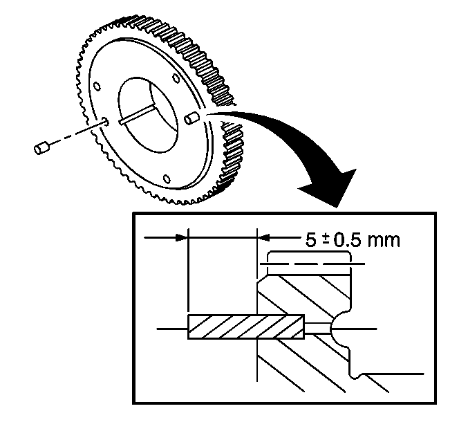
- Install the knock pins in the oil pump drive gear to a height of 4.5-5.5 mm (0.177-0.217 in)
- Install the crankshaft reluctor on the oil pump drive gear. Ensure the reluctor is aligned on the knock pins.
- Install the crankshaft reluctor bolts.
- Install the oil pump drive gear and reluctor assembly to the crankshaft.
- Install the oil pump driven gear.
- While holding the secondary oil pump shaft with a hex driver, install the oil pump driven gear nut.
- Install the upper oil pan. Refer to Upper Oil Pan Replacement .
- Install the engine front cover. Refer to Engine Front Cover Replacement .

Important: The crankshaft reluctor and the oil pump drive gear are timed at the factory. In order to re-establish proper timing, install knock pins in the oil pump drive gear if the crankshaft reluctor was removed from the oil pump drive gear. The knock pins are available through the parts department.

Notice: Use the correct fastener in the correct location. Replacement fasteners must be the correct part number for that application. Fasteners requiring replacement or fasteners requiring the use of thread locking compound or sealant are identified in the service procedure. Do not use paints, lubricants, or corrosion inhibitors on fasteners or fastener joint surfaces unless specified. These coatings affect fastener torque and joint clamping force and may damage the fastener. Use the correct tightening sequence and specifications when installing fasteners in order to avoid damage to parts and systems.
Tighten
Tighten the crankshaft reluctor bolts to 8 N·m (71 lb in).

Important: Do not damage the teeth on the crankshaft reluctor assembly.

Notice: Do not use an impact driver to remove or install the oil pump driven gear nut. Use of an impact driver may shear the oil pump drive gear pin in the crankshaft.
Tighten
Tighten the oil pump driven gear nut to 100 N·m (74 lb ft).
