Supply System
The fuel flows through a pre-filter screen in the tank and to the engine through
the fuel supply lines. There is no lift pump in the fuel tanks or on the frame. The
fuel passes through the base plate of the fuel injector control module
(FICM) to cool the module. From the FICM the fuel flows to the fuel filter assembly,
which combines a water separator, a prime pump and a filter element. Within the assembly,
there is also a fuel heater that operates at fuel temperatures of 6° C (42°
F) and below. An integrated hand pump is used to prime the fuel system after changing
the fuel filter or servicing the fuel system. The fuel injection pump at the front
of the engine valley includes a fuel supply pump and a high-pressure pump. Fuel is
drawn to the supply pump from the primary fuel tank by the supply pump and delivered
to the high-pressure pump.
High Pressure System
The much larger section of the pump assembly is the high-pressure fuel injection
pump. The pump is engine-driven by the camshaft gear. From the high-pressure pump,
the fuel flows through the junction block. The junction block routes pressurized fuel
to both common fuel rails. Each common fuel rail supplies one bank of four fuel injectors.
Return System
The Fuel Return System routes fuel from the fuel injectors, the junction block,
and the fuel injection pump. The return fuel travels to the fuel cooler and then to
the fuel tank. This fuel is used to cool and lubricate the injection pump and the
injectors.
From the Engine to the Tank
- Disconnect the return line at the engine, metal collar.
- Remove the fuel filler cap.
- Apply 1 psi air at the fuel return line that leads back to the
tank.
- Listen at filler tube for air.
- If air is present, return line is okay.
If air is not present,
disconnect the return line at the sender assembly.
- Retest using 1 psi at the fuel return line back to the tank.
| • | If air is present, the return line is okay. Check and replace the sender
assembly. |
| • | If air is not present, repair the restriction in the return line. |
From the Engine to the Injector Spill Lines

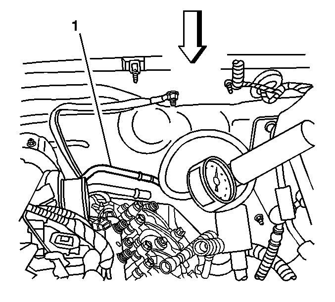
- Disconnect the fuel return line (1)
at the engine. Refer to
Metal Collar Quick Connect Fitting Service
.
- Remove the air duct from the air cleaner assembly to the turbo inlet.
- Remove the air intake pipe. Refer to
Air Intake Pipe Replacement
.

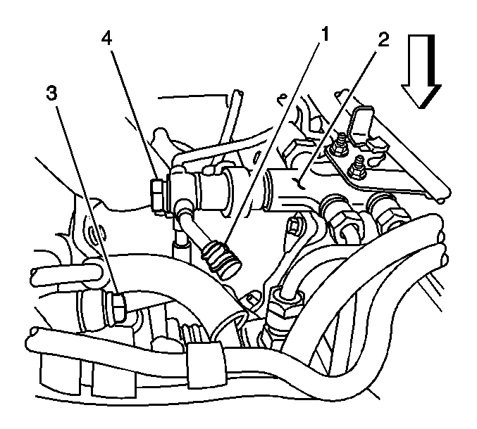
- Remove
the fuel return rubber hose of the fuel injection pump from the junction block (2).
Cap the fitting on the block with a 3/8 inch rubber cap (1) to prevent
fuel leakage.
- Install the J 23738-A
Vacuum
Pump at the fuel return pipe.
- Apply 15 inches Hg of vacuum to the pipe.
| • | If the vacuum holds, go to step 13. |
| • | If the vacuum does not hold, go to step 7. |
- Remove the generator. Refer to
Generator Replacement
in Engine Electrical.

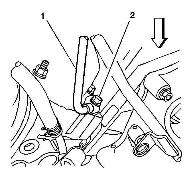
- Remove the fuel return line (1) connecting
the right front and left rear cylinder heads.

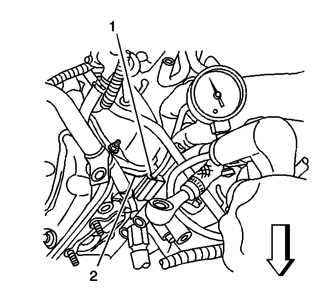
- Install the J 23738-A
onto the right front cylinder head return port (1).
- Apply 15 inches Hg of vacuum to the port.
| • | If the vacuum holds, go to step 11. |
- Install the J 23738-A
onto
the left rear cylinder head return port.

- Remove
the cap (1) from the junction block (2).
- Apply 15 inches Hg of vacuum to the port.
| • | If the vacuum holds, replace the leaking fuel return line between the
cylinder heads. |
- Reinstall the fuel injection pump fuel return hose on the junction block
and clamp the hose.
- Install the air duct on the air cleaner assembly to the turbo inlet.
- Install the air intake pipe. Refer to
Air Intake Pipe Replacement
.
- Reinstall the fuel return line to the engine. Refer to
Metal Collar Quick Connect Fitting Service
.
- Install the generator. Refer to
Generator Replacement
in Engine Electrical.
- Start and idle the engine, and check for leaks.


