Removal Procedure
Important: The fuel rail for the 5.3L regular production option (RPO) L59 (VIN Z) is compatible with fuel that has a composition of up to 85 percent Ethanol (E85). Because of this, the fuel rail will be serviced as an entire assembly, that includes both the left and right rail assemblies and the crossover pipe rail.
- Remove the engine sight shield. Refer to Upper Intake Manifold Sight Shield Replacement in Engine Mechanical - 4.8L, 5.3L, and 6.0L.
- Relieve the fuel system pressure. Refer to Fuel Pressure Relief .
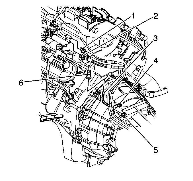
- Disconnect the fuel feed (1) and the fuel return (2) pipes from the fuel rail.
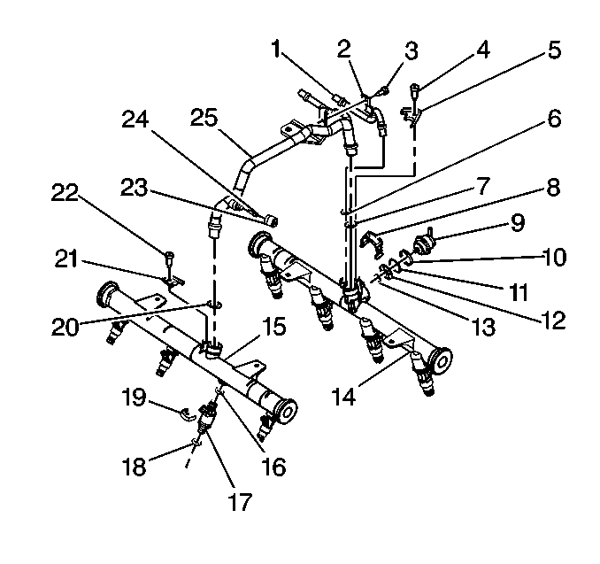
- Remove the fuel return pipe attaching screw (3) and the fuel return pipe retainer (2).
- Remove the fuel return pipe (1).
- Remove and discard the fuel return pipe O-ring (6).
- Remove the fuel pressure connection core assembly (24) from the crossover pipe rail (25).
- Remove the retaining clip attaching screw (22) and the crossover fuel pipe retainer clip (21).
- Remove the retaining clip attaching screw (4) and the crossover fuel pipe retainer clip (5).
- Remove the crossover pipe rail assembly (25) from the left hand rail assembly (14) and the right hand rail assembly (15).
- Remove and discard the crossover fuel pipe O-rings (7, 20).


Installation Procedure
- Lubricate the NEW crossover fuel pipe O-rings (7, 20) with clean engine oil.
- Install the NEW crossover fuel pipe O-rings (7, 20) onto the crossover pipe rail assembly (25).
- Install the crossover pipe rail assembly (25) to the left hand rail assembly (14) and the right hand rail assembly (15).
- Install the crossover fuel pipe retainer clip (21). Loosely install the retaining clip attaching screw (22).
- Lubricate the NEW fuel return pipe O-ring (6) with clean engine oil.
- Install the NEW fuel return pipe O-ring (6) on the fuel return pipe (1).
- Install the fuel return pipe (1).
- Install the fuel return pipe retainer (2). Loosely install the fuel return pipe attaching screw (3).
- Install the crossover fuel pipe retainer clip (5). Loosely install the retaining clip attaching screw (4).
- Tighten the crossover fuel pipe retainer clip attaching screws to 3.8 N·m (34 lb in).
- Tighten the fuel return pipe attaching screw to 5 N·m (44 lb in).
- Install the fuel pressure connection core assembly (24) to the crossover pipe rail assembly (25).
- Connect the fuel return (2) and fuel feed (1) pipes to the fuel rail.
- Tighten the fuel fill cap.
- Connect the negative battery cable. Refer to Battery Negative Cable Disconnection and Connection in Engine Electrical.
- Use the following procedure in order to inspect for leaks:
- Install the fuel pressure connection cap.
- Install the engine sight shield. Refer to Upper Intake Manifold Sight Shield Replacement in Engine Mechanical - 4.8L, 5.3L, and 6.0L.

Notice: Use the correct fastener in the correct location. Replacement fasteners must be the correct part number for that application. Fasteners requiring replacement or fasteners requiring the use of thread locking compound or sealant are identified in the service procedure. Do not use paints, lubricants, or corrosion inhibitors on fasteners or fastener joint surfaces unless specified. These coatings affect fastener torque and joint clamping force and may damage the fastener. Use the correct tightening sequence and specifications when installing fasteners in order to avoid damage to parts and systems.
Important: When installing the retaining clip attaching screws for the crossover pipe, always start them by hand. This will prevent consequent stripping of the threads in the rail.
Important: When installing the retaining clip attaching screws for the crossover pipe, always start them by hand. This will prevent consequent stripping of the threads in the rail.
Tighten

| 14.1. | Turn ON the ignition, with the engine OFF, for 2 seconds. |
| 14.2. | Turn OFF the ignition for 10 seconds. |
| 14.3. | Turn ON the ignition, with the engine OFF. |
| 14.4. | Inspect for fuel leaks. |
