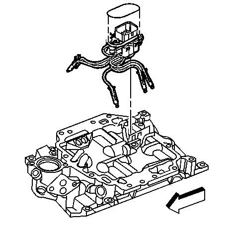
Fuel Meter Body Assembly Replacement 4.3L (RPO L35) Engine
Removal Procedure
Important: An 8-digit part identification number is on a mylar label affixed
to the fuel meter body assembly. Refer to this number if service or part replacement
is required.

- Relieve the fuel system
pressure. Refer to
Fuel Pressure Relief
.
- Remove the upper intake manifold. Refer to
Upper Intake Manifold Replacement
in Engine Mechanical - 4.3L.
Notice: Do not use any solvent that contains Methyl Ethyl Ketone
(MEK). This solvent may damage fuel system components.
- Before removal, clean the fuel meter body with a spray type engine
cleaner, such as GM X-30A or equivalent, if necessary. Follow the package
instructions. Do not soak the fuel meter body in liquid cleaning solvent.
- Remove and discard the fuel meter body seal.
Notice: Cover the injector sockets in order to prevent dirt and other contaminants
from entering the open fuel passages.
Important: When disconnecting the poppet nozzles, remember the sequence in order
to ensure correct poppet nozzle placement to each cylinder.
- Squeeze the poppet nozzle locking tabs together while lifting
the nozzle out of the casting socket.
- Remove the fuel meter body from the bracket by releasing the lock
tabs on the bracket.
Installation Procedure

- Install the fuel meter
body in the intake manifold.
- Push the fuel meter body into the bracket. Make sure all of the
tabs are locked into place.
Caution: Verify that the poppet nozzles are firmly seated and locked in their
casting sockets in order to reduce the risk of fire and personal injury. An
unlocked poppet nozzle could work loose from its socket and produce a fuel
leak.
Important: The fuel meter body is numbered in order to indicate the poppet nozzle
order.
- Install the poppet nozzles into the proper lower intake manifold casting
sockets.
- Inspect the poppet nozzles in order to ensure the nozzles are
firmly seated and locked in the casting sockets.
- Install a NEW fuel meter body seal.
- Install the upper intake manifold. Refer to
Upper Intake Manifold Replacement
in Engine Mechanical - 4.3L.
- Connect the negative battery cable. Refer to
Battery Negative Cable Disconnection and Connection
in Engine
Electrical.
- Tighten the fuel fill cap.
- Test for fuel leaks using the following procedure:
| 9.1. | Turn ON the ignition, with the engine OFF, for 2 seconds. |
| 9.2. | Turn OFF the ignition for 10 seconds. |
| 9.3. | Turn ON the ignition with the engine OFF. |
| 9.4. | Inspect for fuel leaks. |
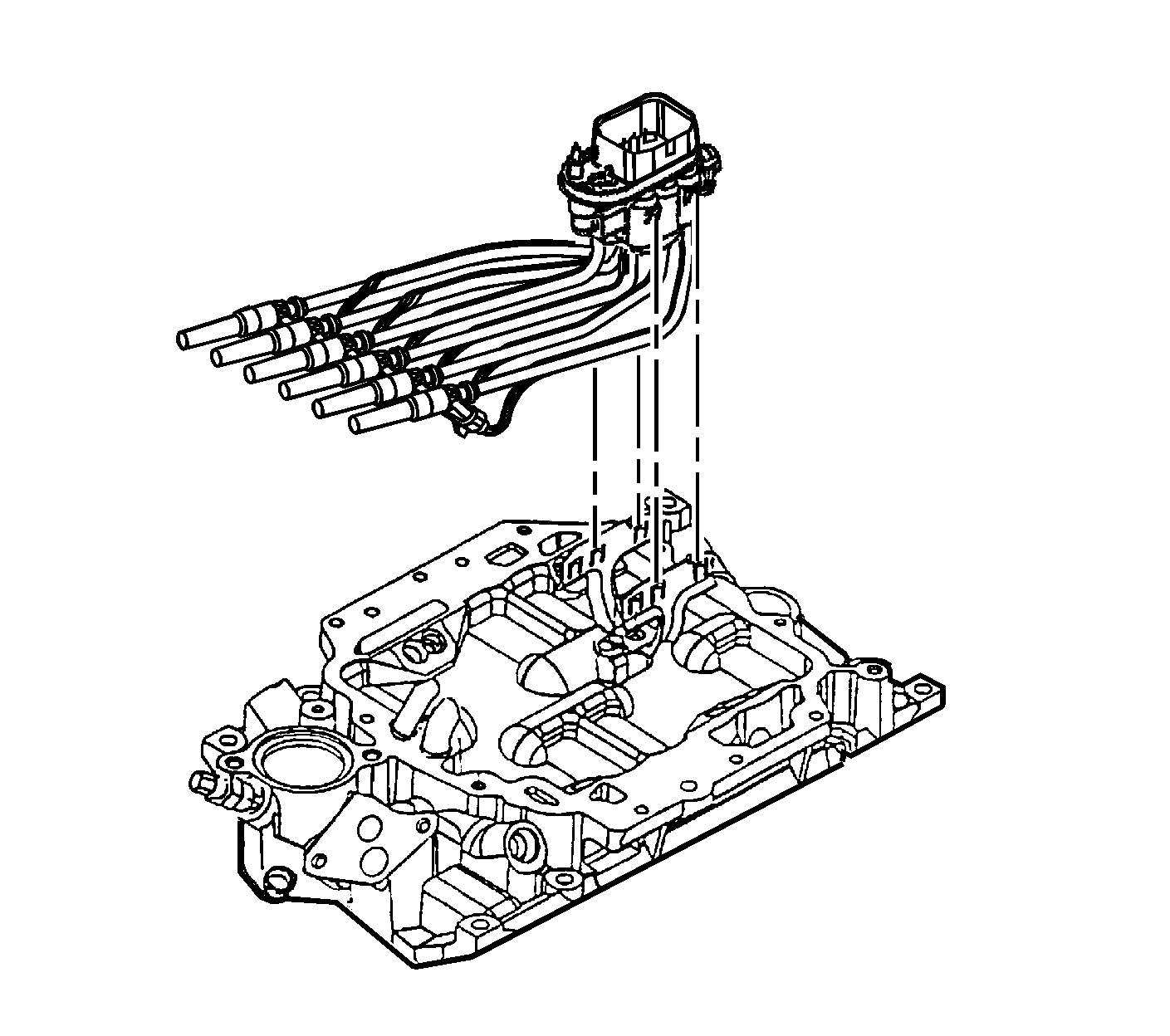
Fuel Meter Body Assembly Replacement 4.3L (RPO LU3) Engine
Removal Procedure
Important: An 8-digit part identification number is on a mylar label affixed to
the fuel meter body. Refer to this number if service or part replacement is required.

- Relieve the fuel system pressure. Refer
to
Fuel Pressure Relief
.
- Remove the upper intake manifold. Refer to
Upper Intake Manifold Replacement
in Engine Mechanical - 4.3L.
- Remove and discard the fuel meter body seal.
- Remove the injectors from the lower intake manifold bores.
- Remove the MFI (muli-port flexible injection) fuel meter body from the
MFI bracket.
Installation Procedure

Important: The number 3 fuel tube must be positioned behind the number 1 fuel tube to
eliminate interference with the upper intake manifold when installed.
- Position the fuel tubes of the MFI fuel meter body in the forward position.
Important: Ensure the number 3 fuel tube is routed behind the number 1 and number 5 fuel
tubes.
- Install the MFI fuel meter body into the fuel meter body bracket on the lower
intake manifold.
Push down firmly to lock the fuel meter body into the fuel meter body bracket.
- Insert the injectors in the following sequence into the correct injector
bore in the lower manifold.
- Insure the electrical connectors on the injectors are positioned so that
they do not interfere with each other and are pointing towards the center of the intake
manifold.
Rotate the electrical connectors inboard if necessary.
Important: Lack of lubrication will make installation of the upper intake manifold difficult
and may cause damage to the O-ring.
- Lubricate the upper intake manifold O-ring on the fuel meter body with clean
engine oil.
- Install the upper intake manifold. Refer to
Upper Intake Manifold Replacement
in Engine Mechanical - 4.3L.
- Tighten the fuel fill cap.
- Connect the negative battery cable. Refer to
Battery Negative Cable Disconnection and Connection
in Engine Electrical.
- Test for fuel leaks using the following procedure:
| 9.1. | Turn ON the ignition, with the engine OFF, for 2 seconds. |
| 9.2. | Turn OFF the ignition for 10 seconds. |
| 9.3. | Turn ON the ignition with the engine OFF. |
| 9.4. | Inspect for fuel leaks. |


