Locking Differential Assemble 10.5 Inch Axle
- Install the right thrust washer.
- Install the right cam unit. Refer to Cam Unit Assembly in this section.
- Install the following parts:
- Install the left thrust washer.
- Install the left side gear.
- Install the latching bracket assembly.
- Install the governor assembly.
- Install the case halves together.
- Install the differential case screws.
- Install the ring gear and the differential side bearings. Refer to Drive Pinion and Ring Gear Replacement and Differential Side Bearings Replacement .
| • | The reaction blocks |
| • | The reaction block thrust washer |
| • | The pinion yoke |
| • | The pinion gears |
| • | The pinion thrust washers |
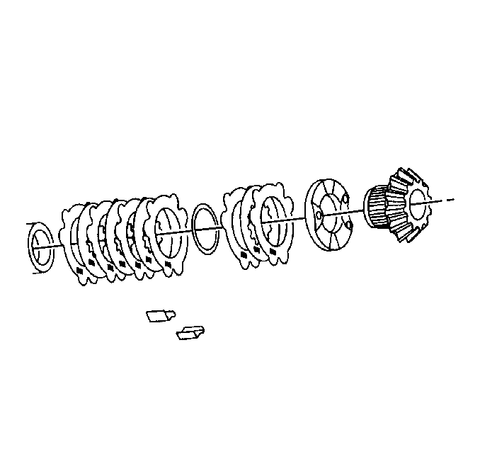
Assemble the plates as shown.
The straight end of the latching bracket spring must be over and outside the governor assembly shaft.
Hold the side gear in the left side case half.
Notice: Use the correct fastener in the correct location. Replacement fasteners must be the correct part number for that application. Fasteners requiring replacement or fasteners requiring the use of thread locking compound or sealant are identified in the service procedure. Do not use paints, lubricants, or corrosion inhibitors on fasteners or fastener joint surfaces unless specified. These coatings affect fastener torque and joint clamping force and may damage the fastener. Use the correct tightening sequence and specifications when installing fasteners in order to avoid damage to parts and systems.
Tighten
Tighten the differential case screws to 17 N·m (13 lb ft).
Locking Differential Assemble 8.6, 9.5, 11.5 Inch Axles
Important: The left and right side gear backlash and thrust block thickness measurement must be completed before the components of the locking differential can be assembled.
- Install the left side gear thrust washer.
- Install the left side gear cam unit and clutch disc assembly.
- Install the right side gear thrust washer.
- Install the right side clutch disc assembly.
- Install the right side gear.
- Install the pinion gear and the pinion thrust washers.
- Rotate the pinion gears and the pinion thrust washers 90 degrees and align the pinion gears with the pinion shaft opening in the differential case.
- Install the thrust block.
- Install the pinion shaft.
- For the 8.6 inch, 9.5 inch axles, install the new pinion shaft lock bolt.
- For the 11.5 inch axle, install the new pinion shaft retaining pin.
- Install the governor assembly.
- Install the governor bushing using a hammer and a brass drift.
- Install the latching bracket assembly.
- Install the latching bracket bushing using a hammer and a brass drift.
- For the 8.6, 9.5 inch axles, tighten the pinion shaft lock bolt.
- Install the ring gear, if necessary. Refer to Drive Pinion and Ring Gear Replacement .
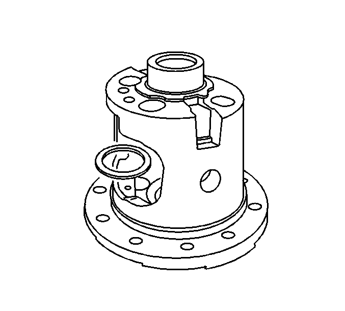
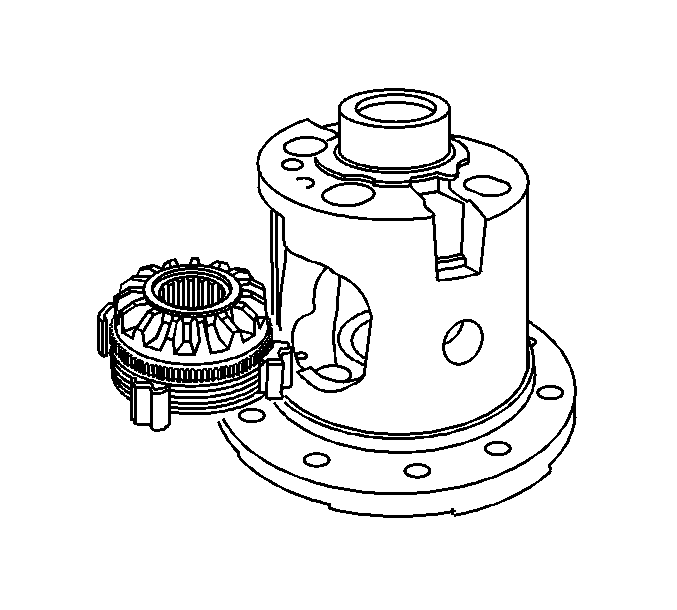
Important: If the original pinion gears and thrust washers are being re-used, install the pinion gears and thrust washers on the same side as when removed.
Place the pinion gears and the pinion thrust washers 180 degrees apart.
The open side of the thrust block must face the window opening.
Tighten the pinion shaft lock bolt finger tight.
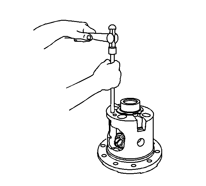
Drive the retaining pin into the differential case using a hammer and drift pin.
Notice: Refer to Fastener Notice in the Preface section.
Specification
Press the bushing into place until there is 0.25-1.27 mm (0.010-0.050 in) of shaft end play.
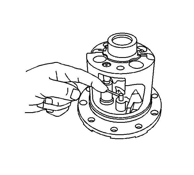
The straight end of the latching bracket spring must be over and outside the governor assembly shaft.
Specification
Press the bushing into place until there is 0.000-0.051 mm (0.000-0.002 in) of shaft end play.
Tighten
| • | For the 8.6 inch axle, tighten the pinion shaft lock bolt to 36 N·m (27 lb ft). |
| • | For the 9.5 inch axle, tighten the pinion shaft lock bolt to 50 N·m (37 lb ft). |
