Assembly of Shift Valve Body
Tools Required
| • | J 33163 Valve Tray Set |
| • | J 43773 Valve Spring Compressor |
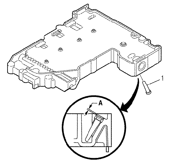
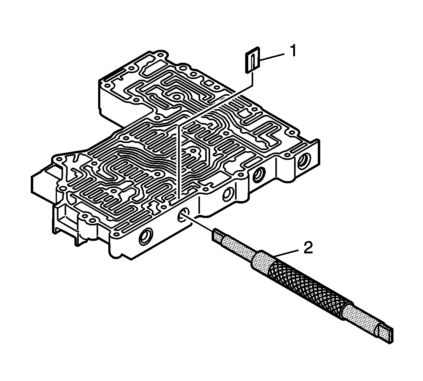
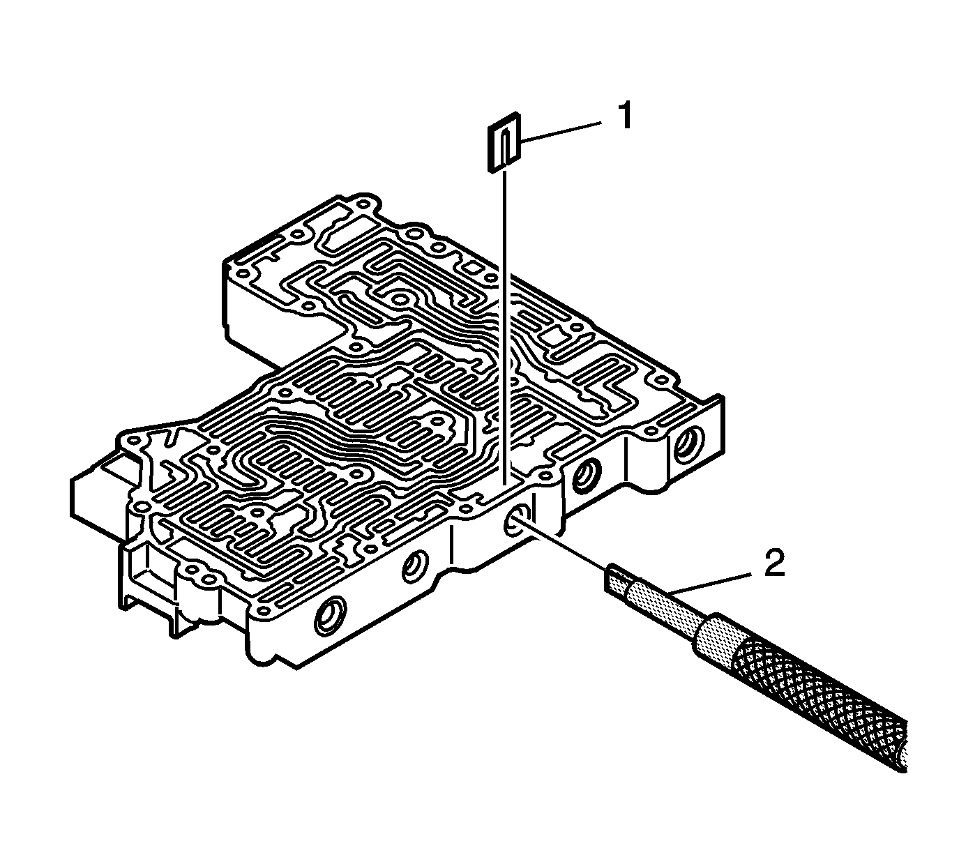
- Install solenoid screen (1).
- Ensure solenoid screen (1) is installed to a depth of 0.50-1.00 mm (0.20-0.039 inch) (Dimension A) below the shift valve body surface, as shown.
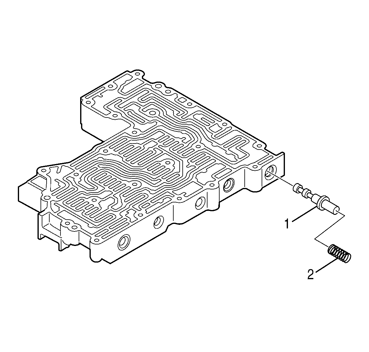
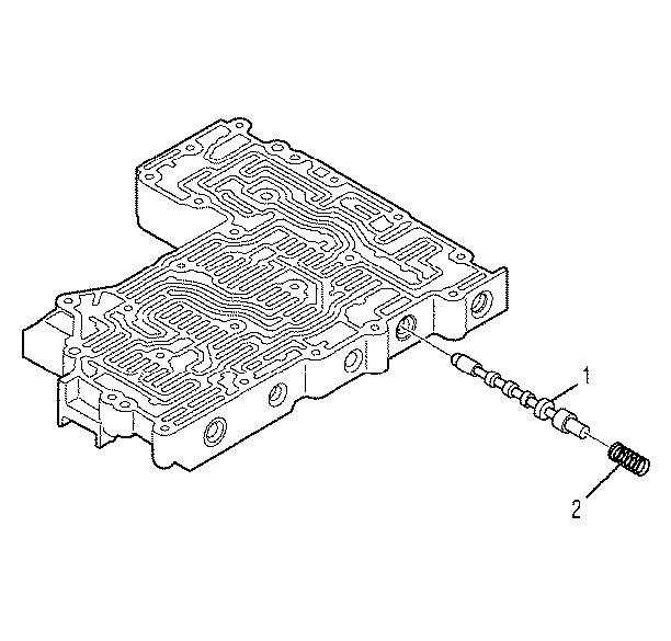
- Install control main valve (1) and spring (2).
- Compress the spring with tool J 33163 (2).
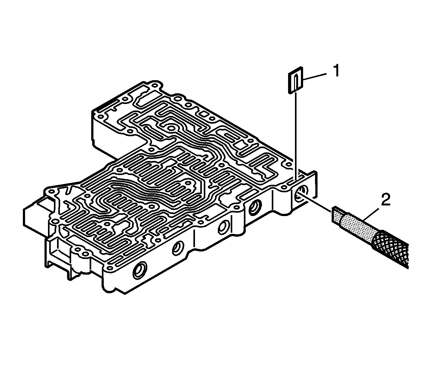
- Install retaining clip (1). Ensure retaining clip (1) is below the valve body surface.
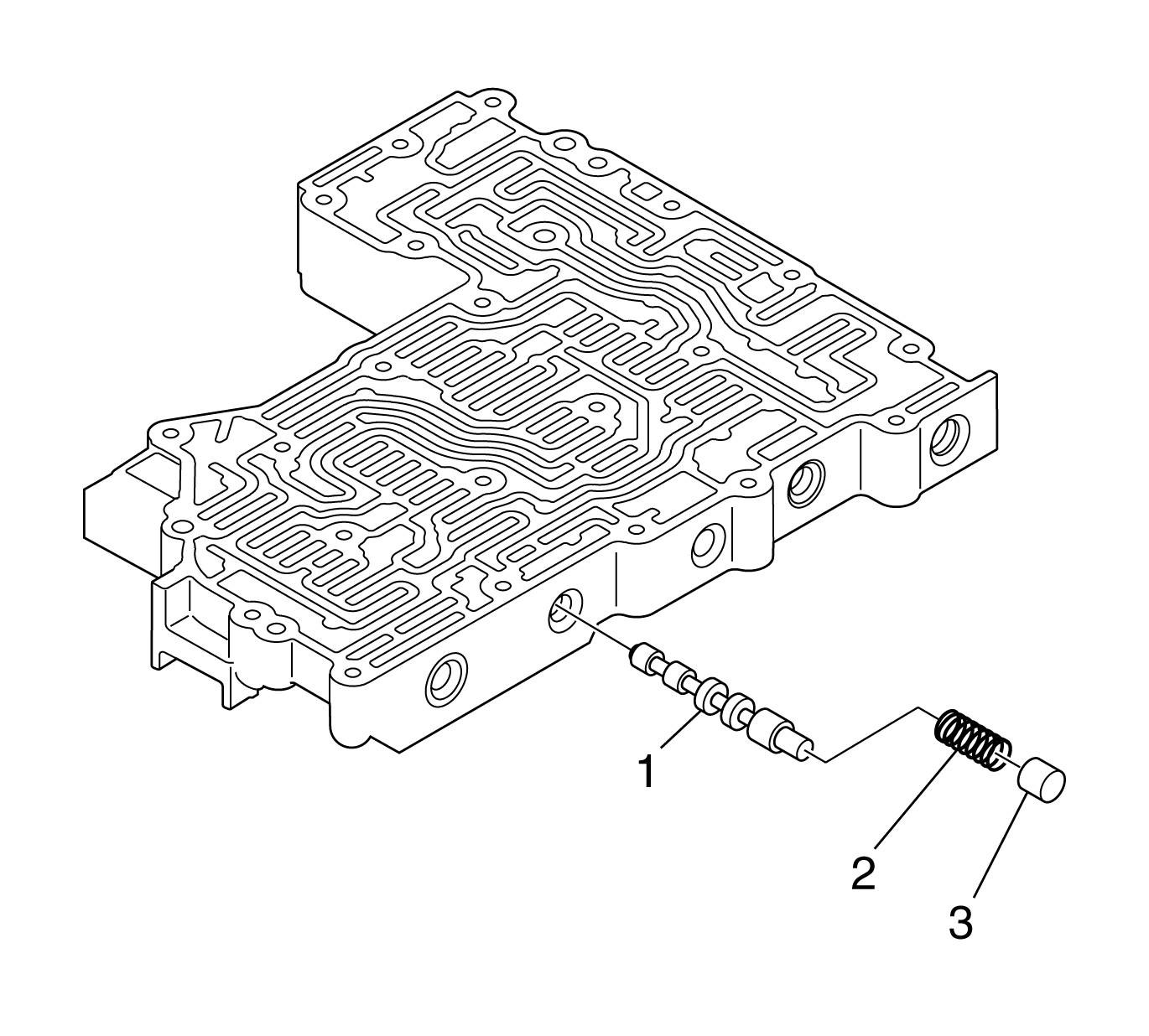
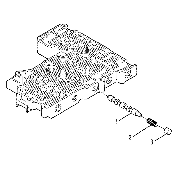
- Install D shift valve (1), spring (2), and plug (3).
- Compress the spring with tool J 43773 (2)
- Install retaining clip (1). Ensure the retaining clip is below the valve body surface.
- Install E shift valve (1), spring (2), and plug (3).
- Compress the spring with tool J 43773 (2)
- Install retaining clip (1). Ensure the retaining clip is below the valve body surface.
- Install C shift valve (1), spring (2), and plug.
- Compress the spring with tool J 43773 (2)
- Install retaining clip (1). Ensure the retaining clip is below the valve body surface.
Notice: Refer to Transmission Control Valve Body Overhaul Notice in the Preface section.
Assembling the Main Valve Body
Tools Required
| • | J 33163 Valve Tray Set |
| • | J 43773 Valve Spring Compressor |
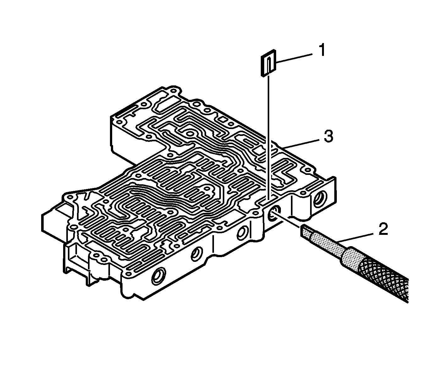
- Install exhaust backfill valve (1) and spring (2).
- Compress the spring with tool J 43773 (2).
- Install retaining clip (1). Ensure retaining clip (1) is below the valve body surface.
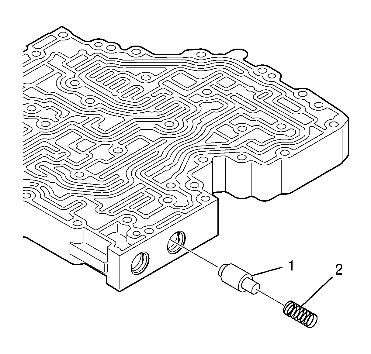
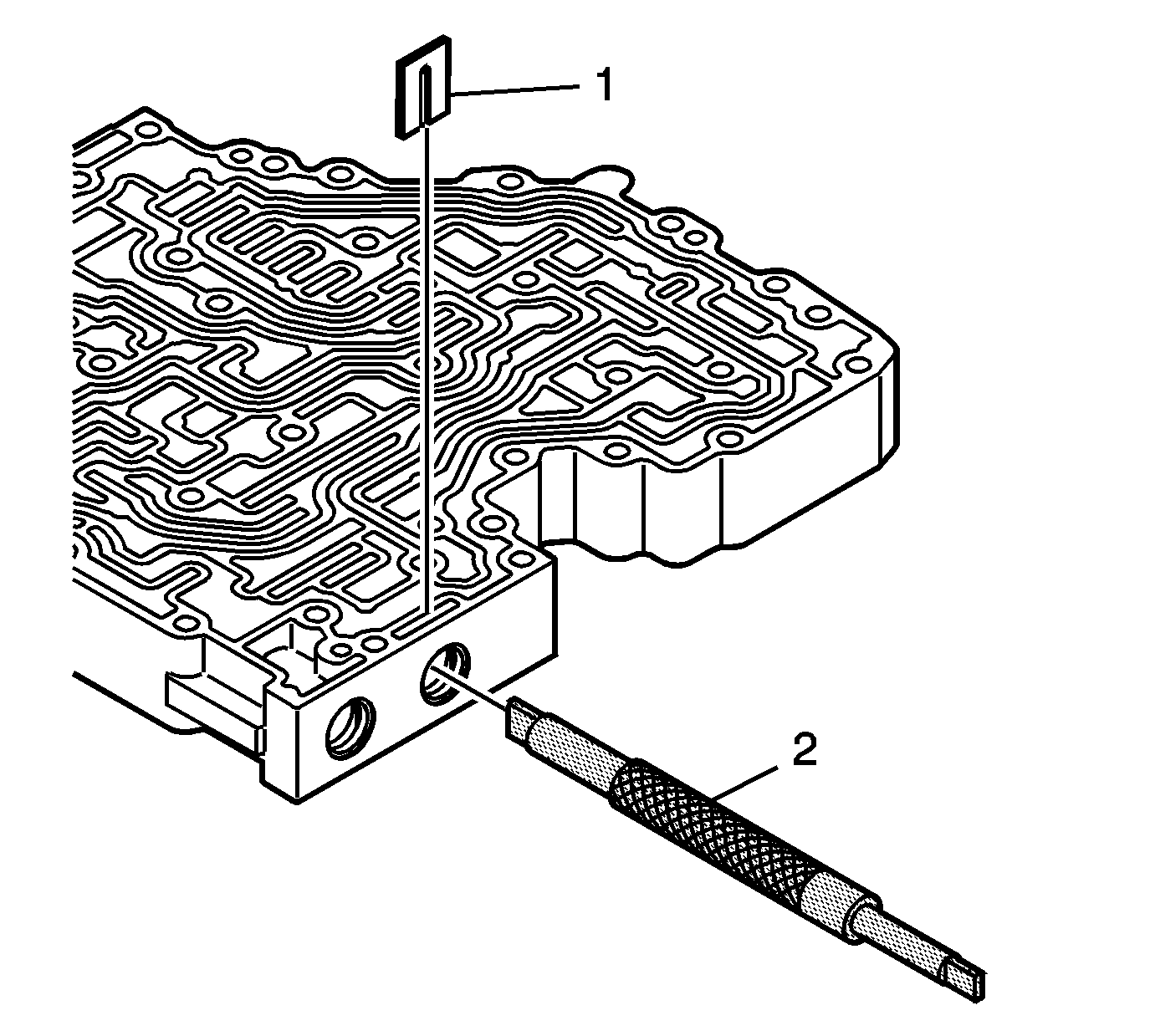
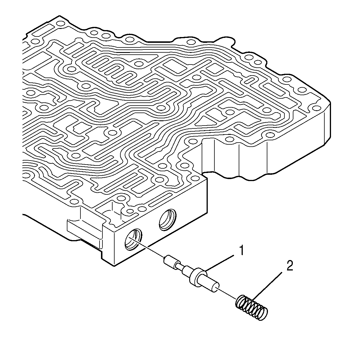
- Install control relief valve (1) and spring (2).
- Compress the spring with tool J 43773 (2).
- Install retaining clip (1). Ensure retaining clip (1) is below the valve body surface.
Notice: Refer to Transmission Control Valve Body Overhaul Notice in the Preface section.
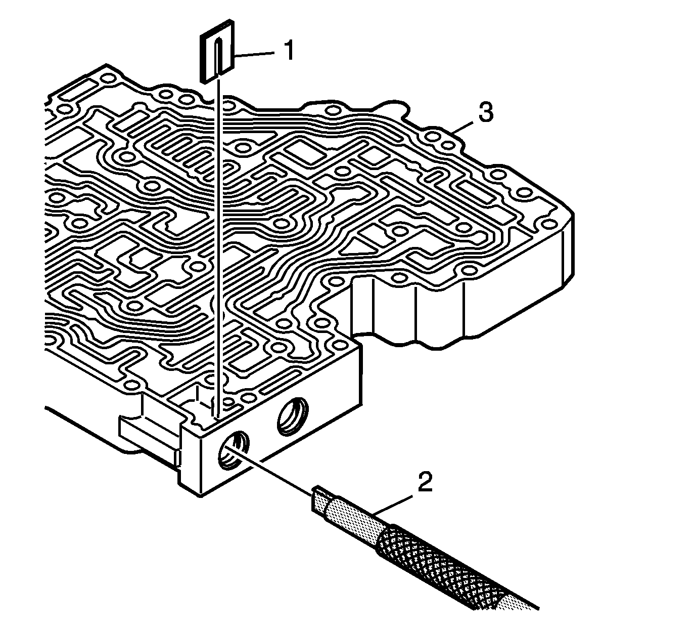
Dowel Pin Replacement
Tools Required
J 43779 Dowel Pin Installer
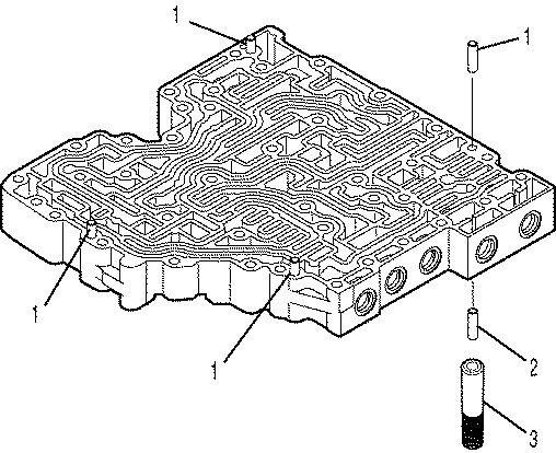
Important: The main valve body has five replaceable dowel pins. Do not replace a dowel pin unless it is damaged.
DO NOT mar the main valve body surface when installing or removing dowel pin(s). Use only gentle tapping on tool J 43779 dowel pin installer. Heavy or continued hammering on tool J 43779 will damage the main housing surface.- Carefully drive out damaged dowel pins.
- Place a replacement dowel pin in tool J 43779 (3).
- Install tool J 43779 (3) with the dowel pin into the dowel pin hole.
- Gently tap tool J 43779 until the tool touches the main valve body surface.
- Ensure the dowel pin is installed to a height of 10.7-11.3 mm (0.42-0.44 inch) above the main valve body surface.
Assembling the Control Valve Module
Tools Required
| • | J 33163 Valve Tray Set |
| • | J 43773 Valve Spring Compressor |
- Position the main valve body assembly (4) on the work table with the hydraulic passages facing up.
- Align separator plate (2) with main valve body dowel pins (3).
- Install separator plate (2).
- Align shift valve body assembly (1) with main valve body dowel pins (3).
- Install shift valve body (1) onto separator plate (2).
- Position the control valve body on the work table so that the main valve body is facing up.
- Install the fourteen bolts (1) fastening the valve bodies together.
- Position the control valve assembly on the work table so that the shift valve body is facing up.
- Install solenoid O-ring (4) onto C ON/OFF shift solenoid (5).
- Align C ON/OFF shift solenoid (5) so that the electrical connector faces the nearest side, as shown.
- Push the solenoid into the valve body until the solenoid seats.
- Install solenoid retainer (2).
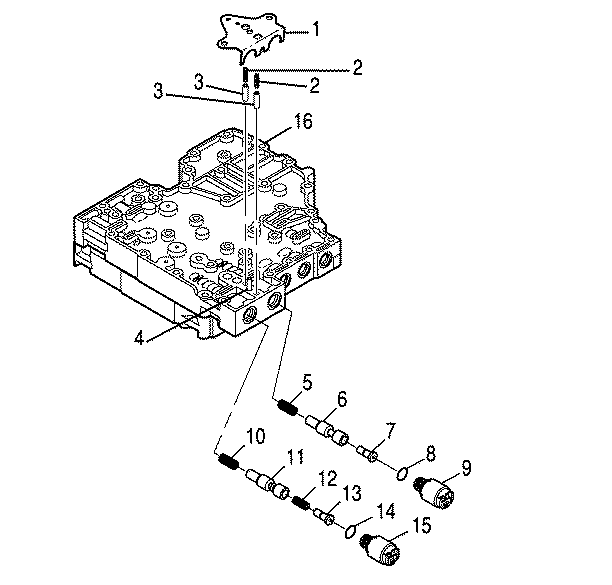
- Position the control valve assembly on the work table so that main valve body (16) is facing up.
- Install solenoid O-ring (14) onto A trim solenoid (15).
- Install spring (10), A trim valve (11), spring (12), if present, and trim gain valve (13).
- Install A trim solenoid (15) so that the electrical connector faces up.
- Install solenoid O-ring (8) onto B trim solenoid (9).
- Install spring (5), B trim valve (6), and trim gain valve (7).
- Install B trim solenoid (9) so that the electrical connector faces up.
- Align two accumulator plugs (3) so that their spring bores face up.
- Install two accumulator plugs (3) and two accumulator springs (2).
- Push A and B trim solenoids (9,15) into their bores until they seat.
- Align A/B solenoid bracket (1) with main valve body dowel pin (4).
- Install A/B solenoid bracket (1) so that the A and B trim solenoids and the accumulator plugs and springs are retained against the valve body.
- Install three bolts (1) through A/B solenoid bracket (2).
- Install solenoid O-ring (3) onto E ON/OFF shift solenoid (4).
- Install solenoid O-ring (2) onto E ON/OFF shift solenoid (4).
- Install E ON/OFF shift solenoid (4) so that the solenoid electrical connector faces up.
- Install solenoid retainer (1).
- Install solenoid O-ring (3) onto D On/OFF shift solenoid (4).
- Install solenoid O-ring (2) onto D ON/OFF shift solenoid (4).
- Install D ON/OFF shift solenoid (4) so that the solenoid electrical connector faces up.
- Install solenoid retainer (1).
- Install solenoid O-ring (6) onto F trim solenoid (7).
- Install solenoid O-ring (5) onto F trim solenoid (7).
- Install F trim spring (2).
- Install F trim valve (3).
- Install F trim sleeve (4).
- Align F trim solenoid (7) so that electrical connector faces up.
- Push F trim solenoid (7) into the valve body until it seats.
- Install solenoid retainer (1).
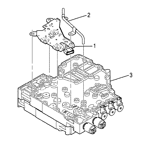
- Align bolts and alignment tab of pressure switch assembly (1) with the pressure switch assembly holes in main valve body (3).
- Install pressure switch assembly (1) onto main valve body (3).
- Install reverse signal tube (2) into the main valve body.
- Install six bolts (1) retaining the pressure switch assembly to the main valve body.
- Install the remaining bolt (1) retaining the reverse signal tube to the main valve body.
- Install bolt (2) retaining the reverse signal tube to the pressure switch assembly.
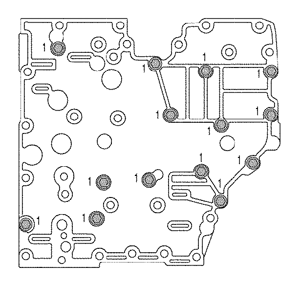
Tighten
Tighten the bolts to 12 N·m (106 lb in).
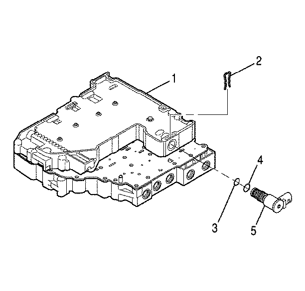
Important: P/N 29536833 is printed on C ON/OFF shift solenoid (5).
O-ring (4) is slightly smaller than O-ring (3)
Notice: Do not damage the solenoid(s) when turning over the control valve assembly.
Important: P/N 29533074 is printed on A trim solenoid (15).
Important: P/N 29533075 is printed on B trim solenoid (9).
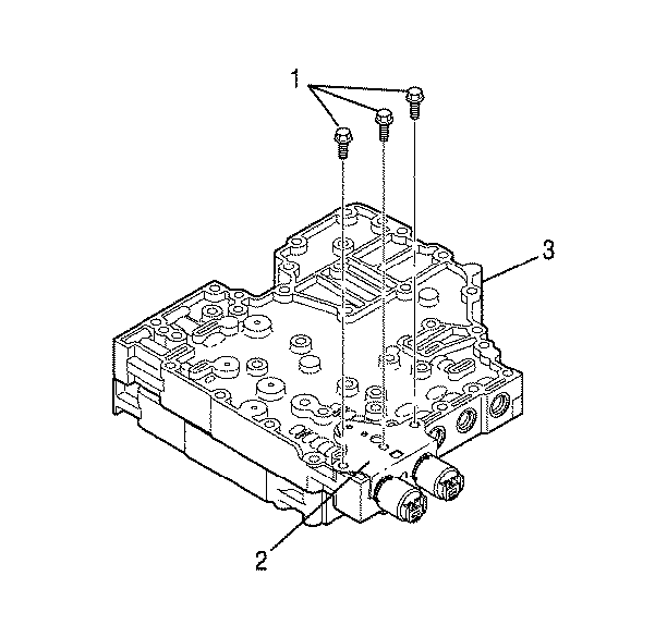
Notice: Use the correct fastener in the correct location. Replacement fasteners must be the correct part number for that application. Fasteners requiring replacement or fasteners requiring the use of thread locking compound or sealant are identified in the service procedure. Do not use paints, lubricants, or corrosion inhibitors on fasteners or fastener joint surfaces unless specified. These coatings affect fastener torque and joint clamping force and may damage the fastener. Use the correct tightening sequence and specifications when installing fasteners in order to avoid damage to parts and systems.
Tighten
Tighten bolts to 12 N·m (106 lb in).
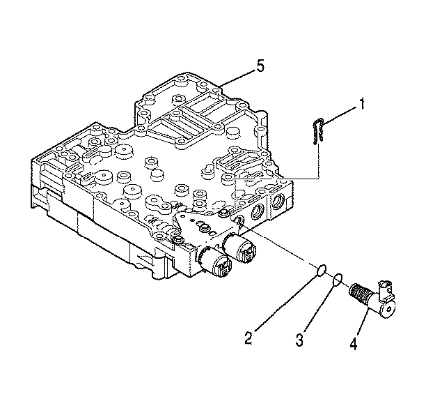
Important: P/N 29536833 is printed on E ON/OFF shift solenoid (4).
Solenoid O-rings are brown. O-ring (3) is slightly larger than O-ring (2).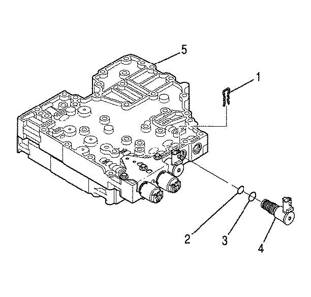
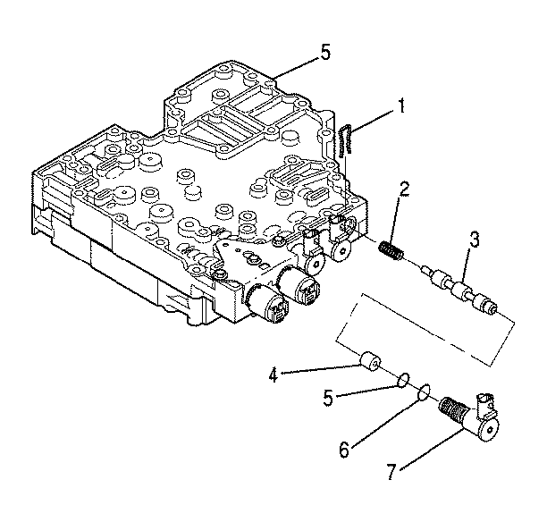
Important: Solenoid O-rings are brown. O-ring (6) is slightly larger than O-ring (5).
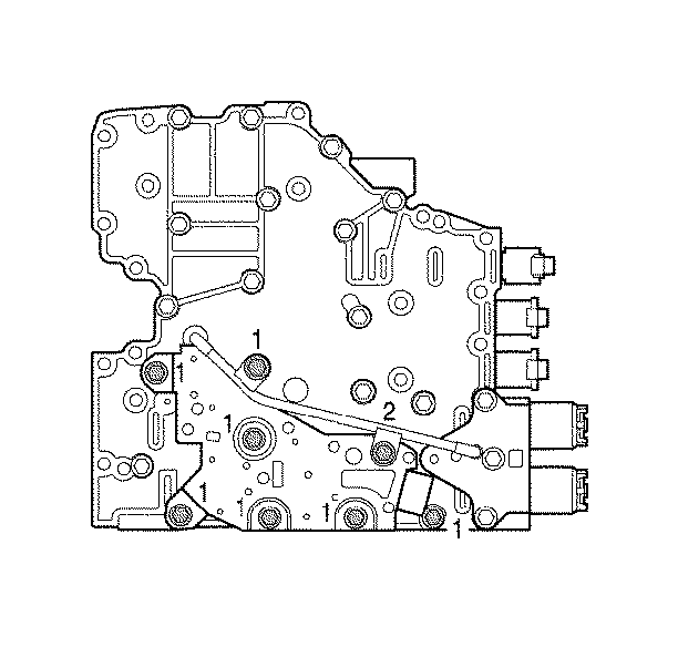
Important: Seven bolts (1) and one bolt (2) retain the reverse signal tube and the pressure switch assembly to the main valve body. Bolt (2) is slightly longer than bolts (1).
Notice: Use the correct fastener in the correct location. Replacement fasteners must be the correct part number for that application. Fasteners requiring replacement or fasteners requiring the use of thread locking compound or sealant are identified in the service procedure. Do not use paints, lubricants, or corrosion inhibitors on fasteners or fastener joint surfaces unless specified. These coatings affect fastener torque and joint clamping force and may damage the fastener. Use the correct tightening sequence and specifications when installing fasteners in order to avoid damage to parts and systems.
Tighten
Tighten bolts (1,2) to 12 N·m (106 lb in).
