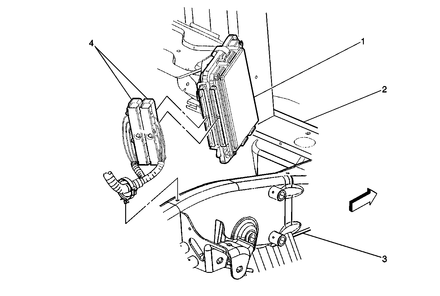
| Figure 1: |
PCM Location
|
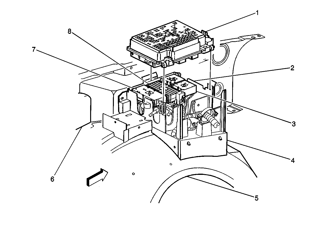
| Figure 2: |
Fuse Block-Underhood
|
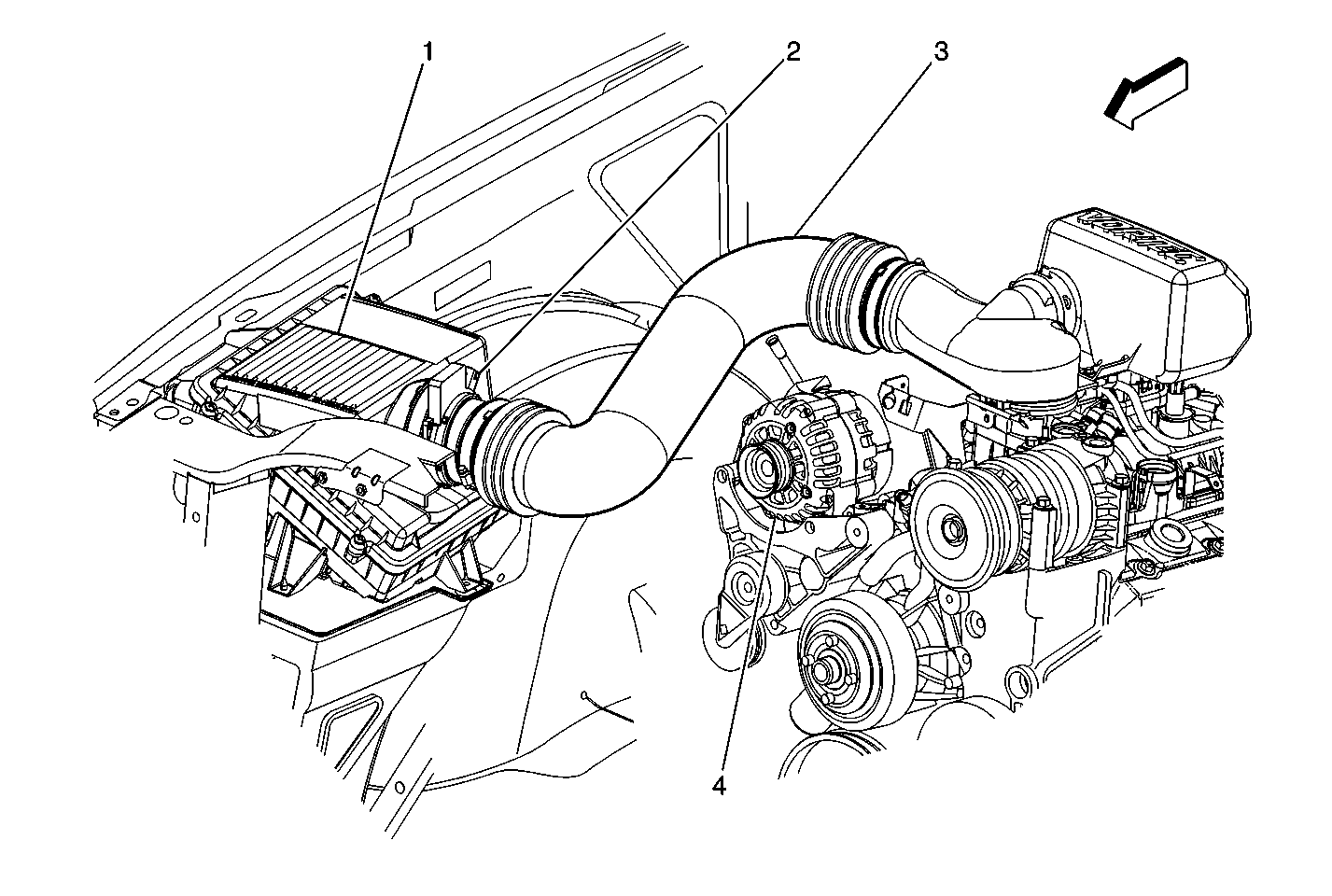
| Figure 3: |
Mass Air Flow (MAF)/Intake Air Temperature (IAT) Sensor Assembly, Generator, Air Cleaner
|
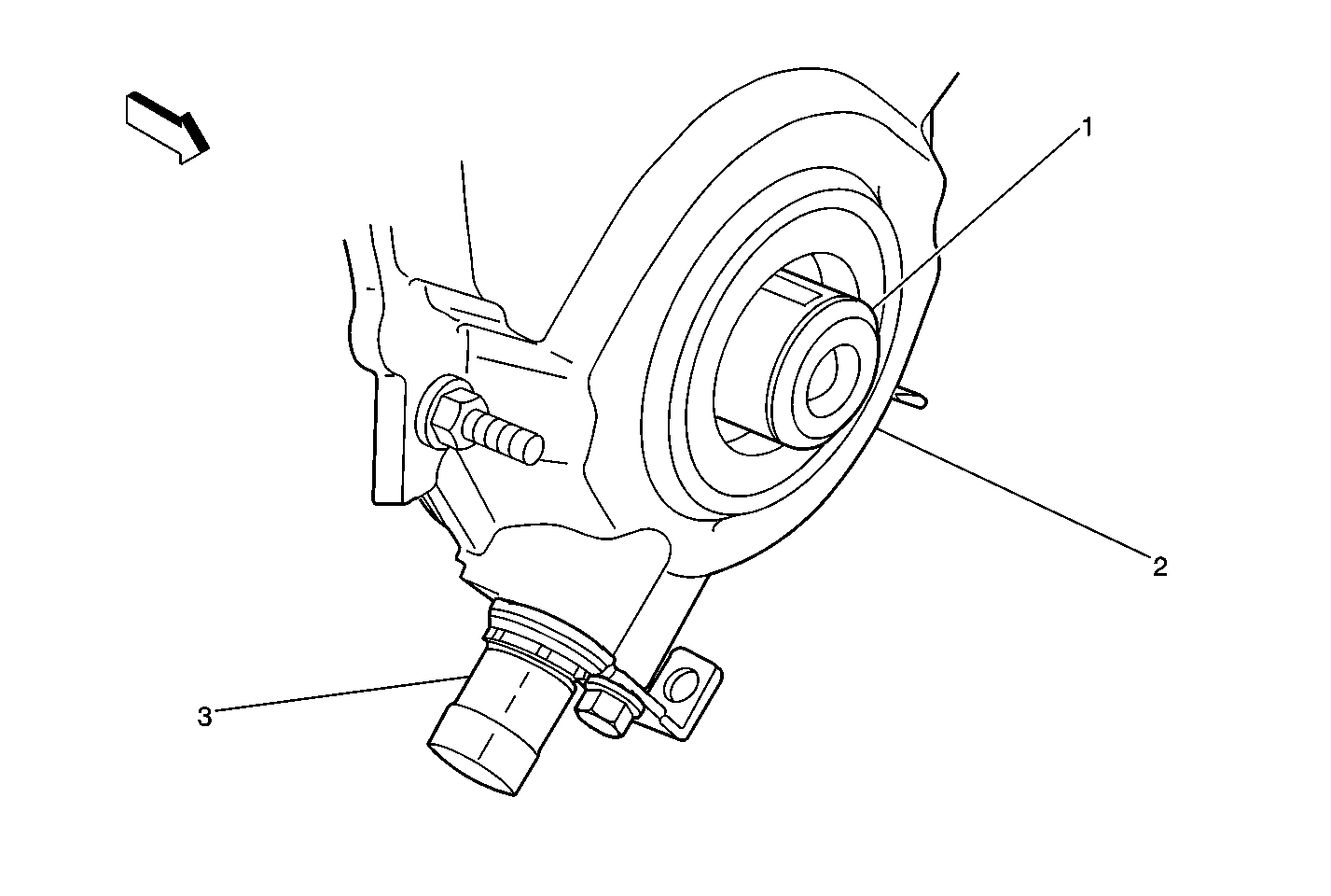
| Figure 4: |
Crankshaft Position (CKP) Sensor
|
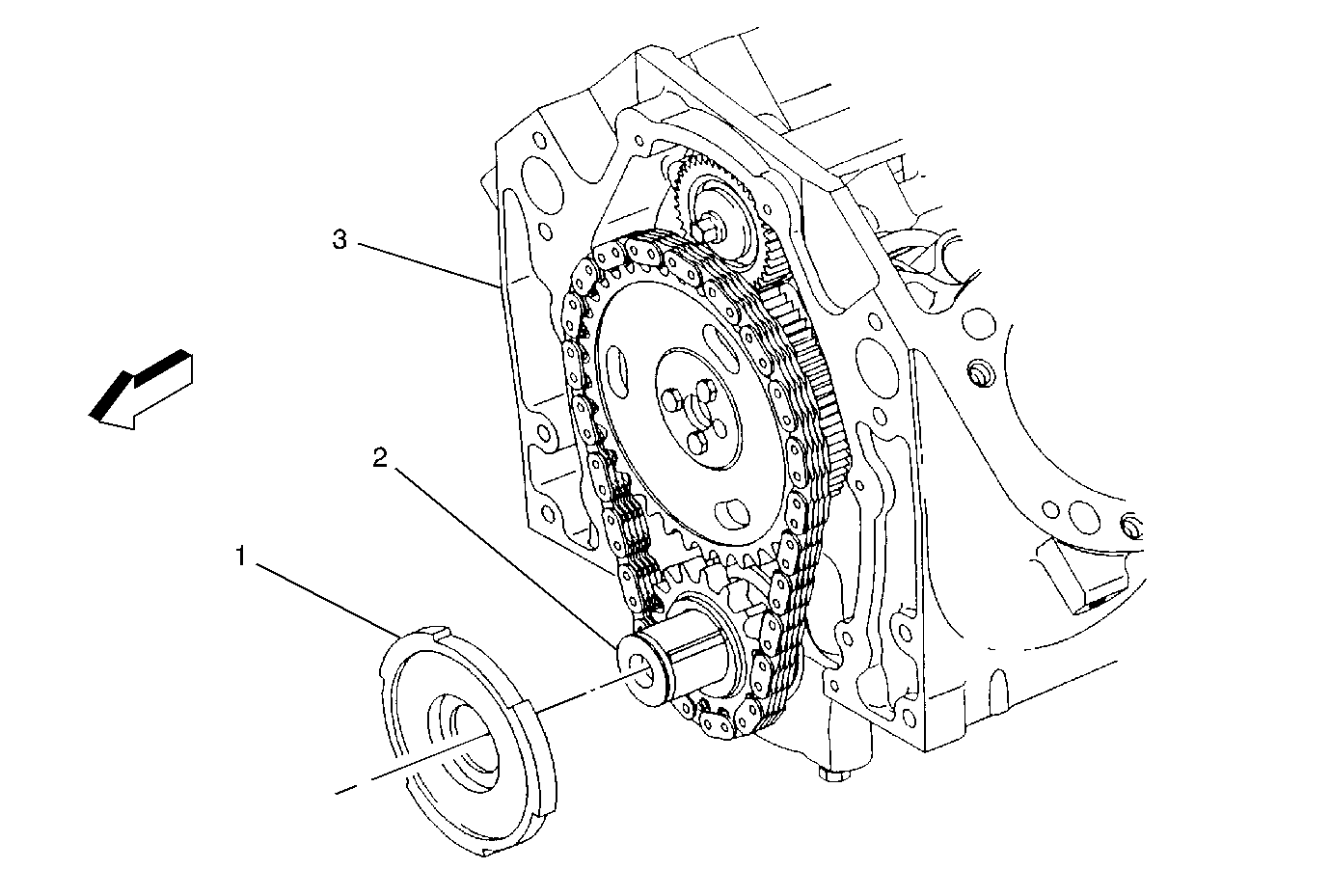
| Figure 5: |
Crankshaft Position (CKP) Reluctor Wheel
|
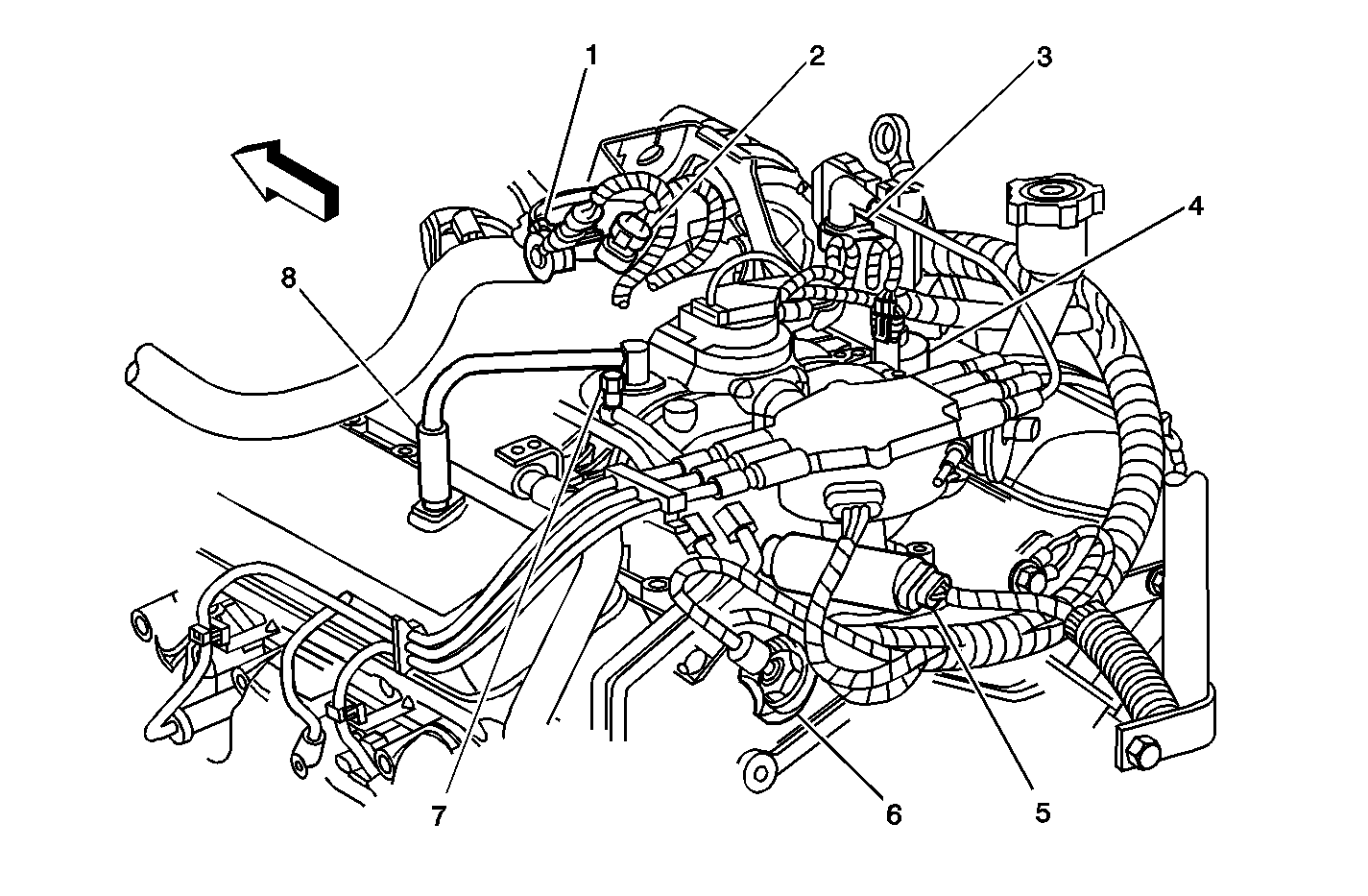
| Figure 6: |
Throttle Position (TP) Sensor, Idle Air Control (IAC) Valve, and Positive Crankcase Ventilation Valve (PCV)
|
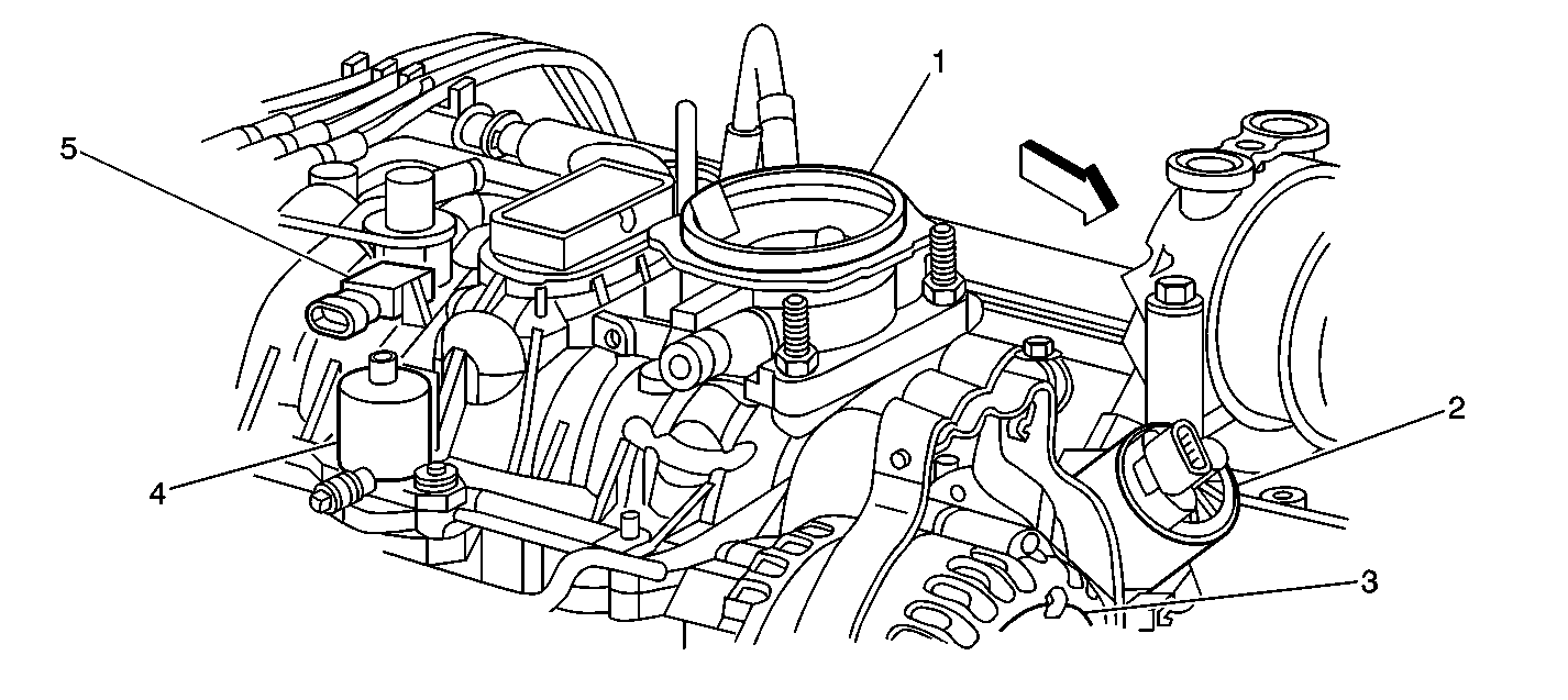
| Figure 7: |
MAP, EGR, Purge Solenoid, and Throttle Body
|
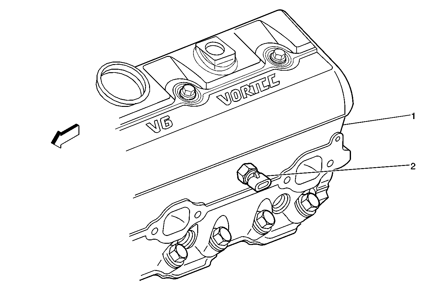
| Figure 8: |
Engine Coolant Temperature (ECT) Sensor
|
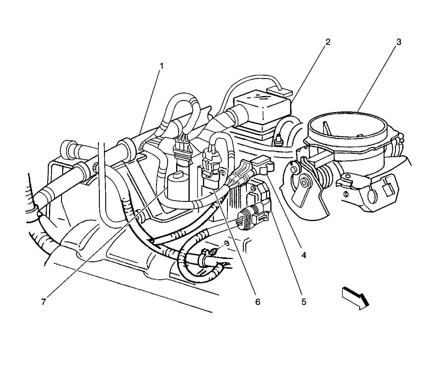
| Figure 9: |
Evaporative (EVAP) Canister Purge Valve
|
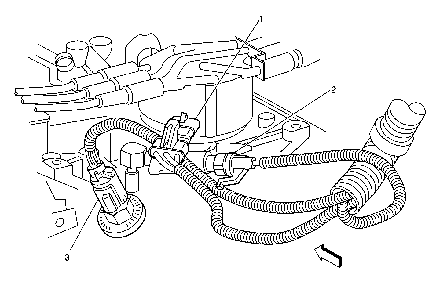
| Figure 10: |
Camshaft Position (CMP) Sensor, Knock Sensor (KS), and Oil Pressure Switch
|
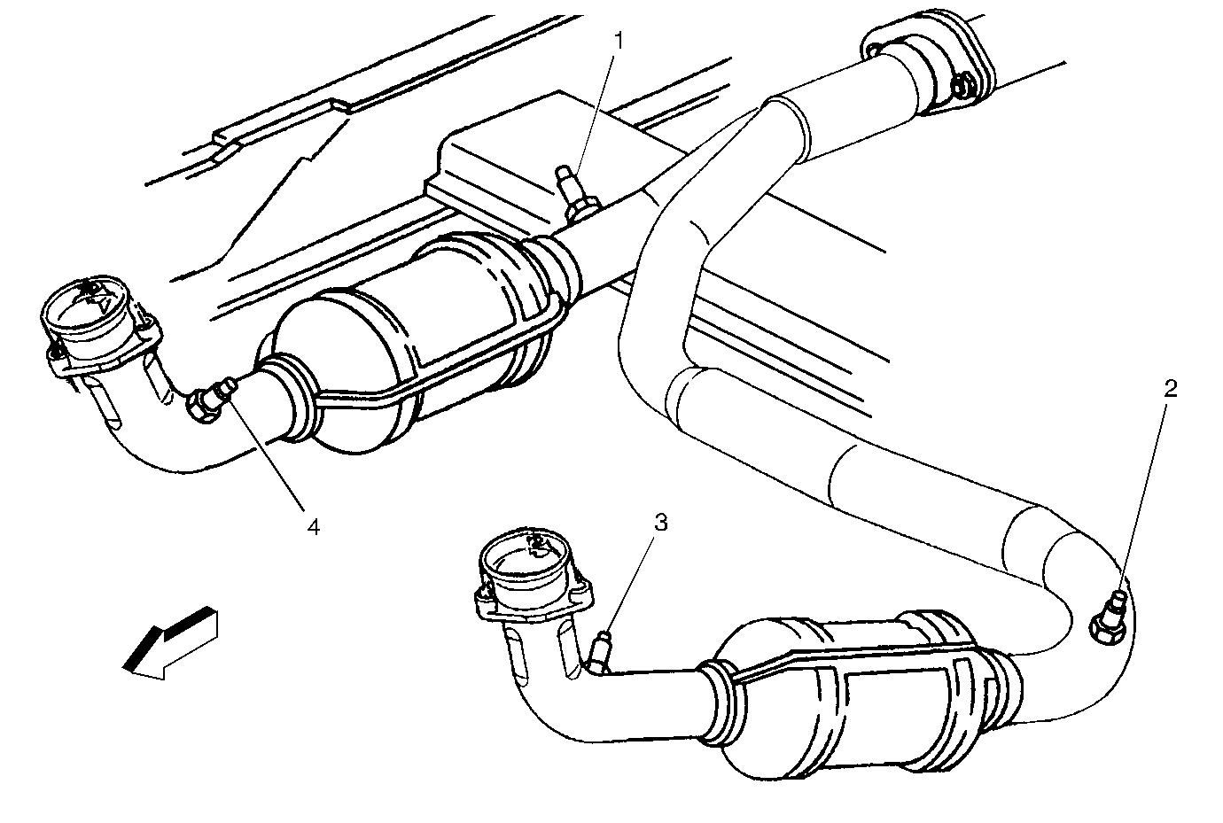
| Figure 11: |
Heated Oxygen Sensors
|
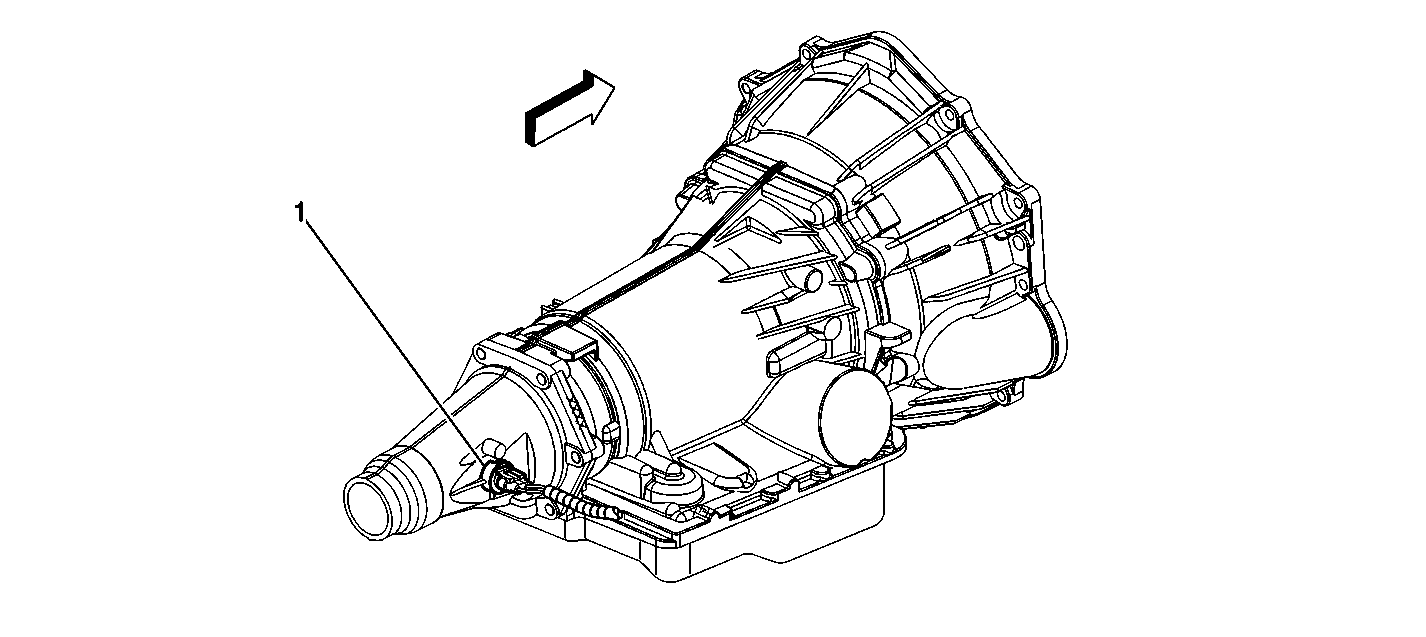
| Figure 12: |
VSS 2 Wheel Drive Automatic Transmission
|
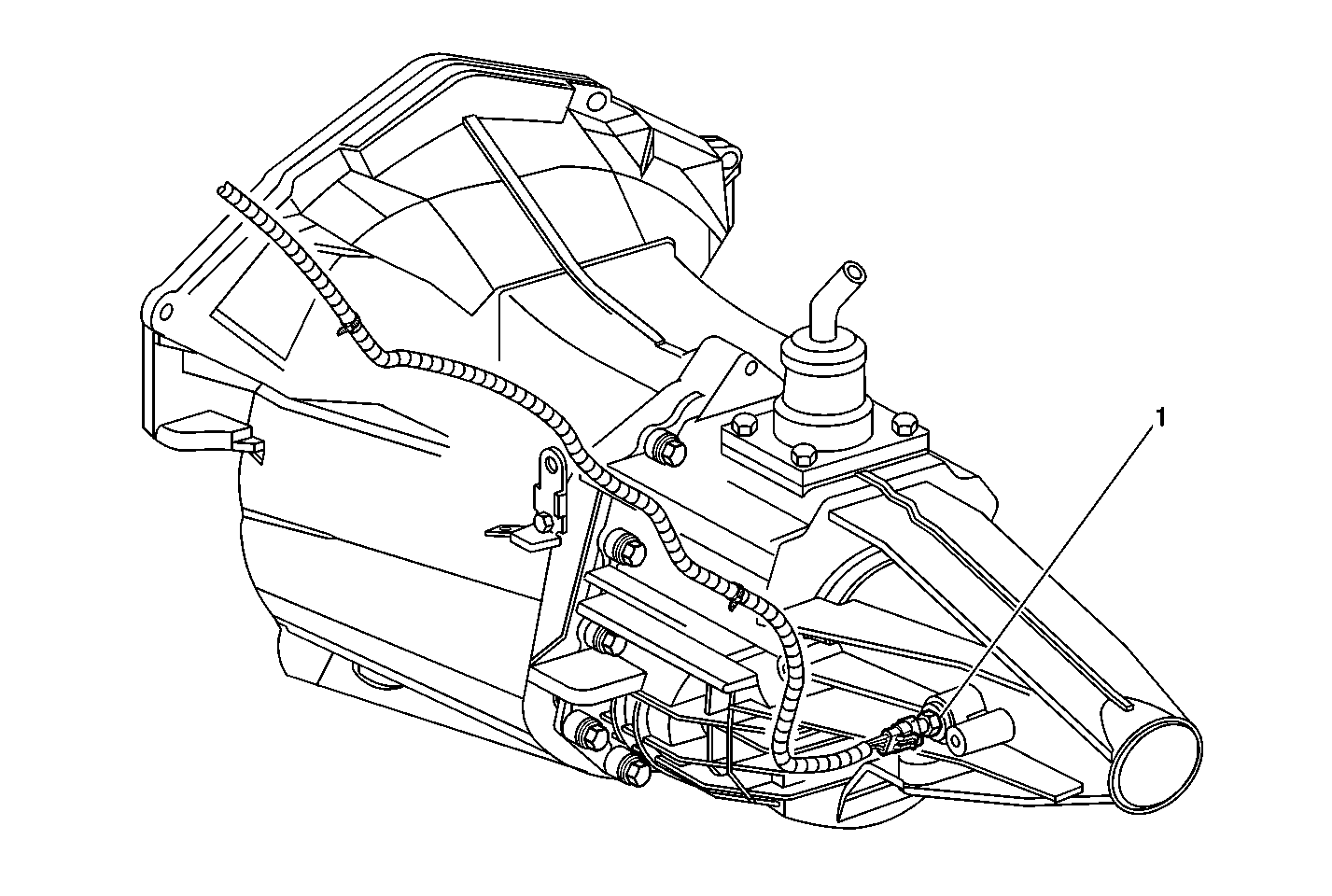
| Figure 13: |
Vehicle Speed Sensor (VSS) - 2 Wheel Drive Manual Transmission
|
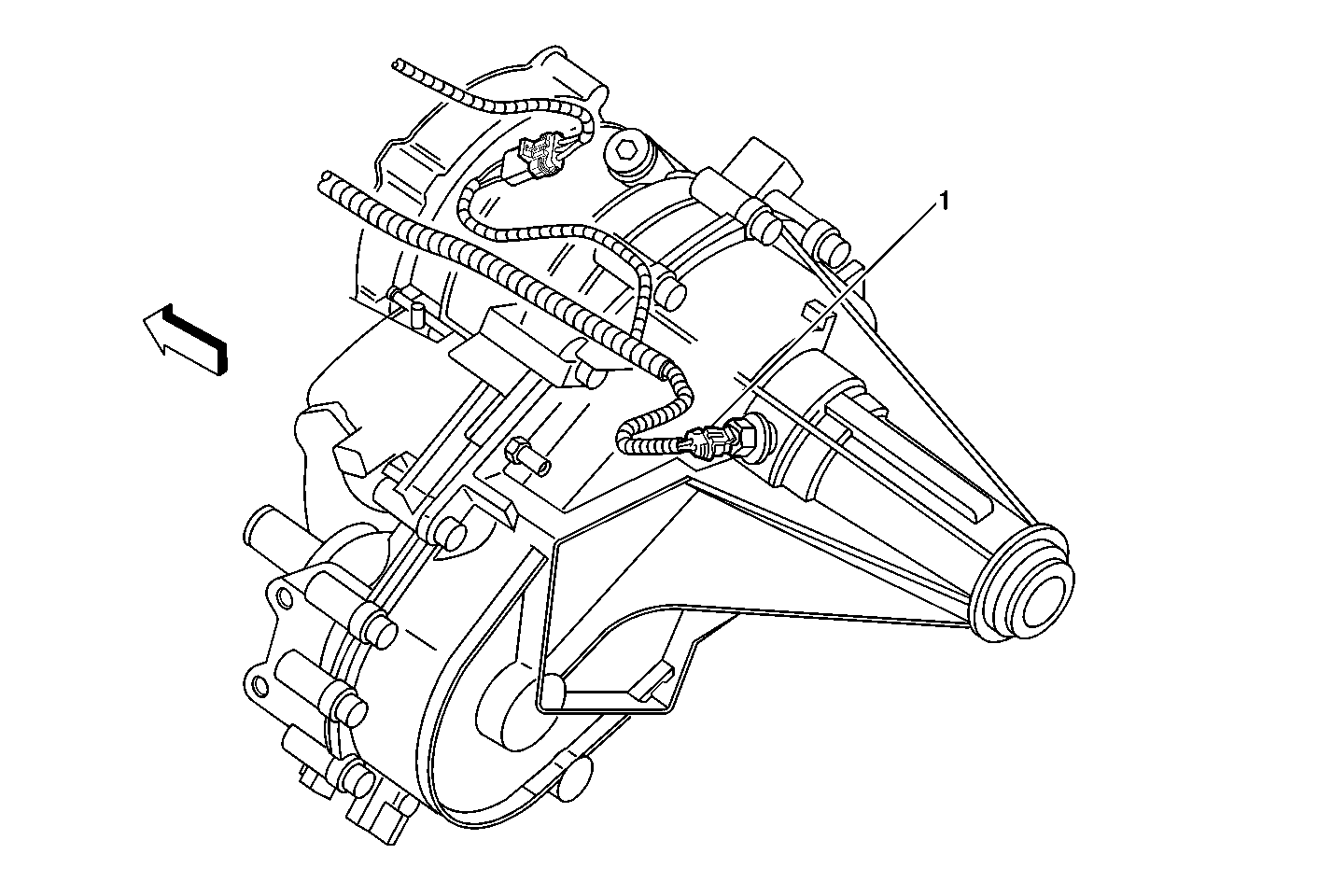
| Figure 14: |
Vehicle Speed Sensor (VSS) - 4 Wheel Drive Automatic Transmission
|
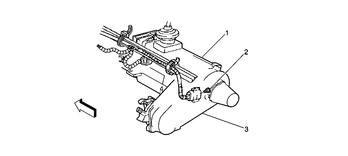
| Figure 15: |
Vehicle Speed Sensor (VSS) - 4 Wheel Drive Manual Transmission
|
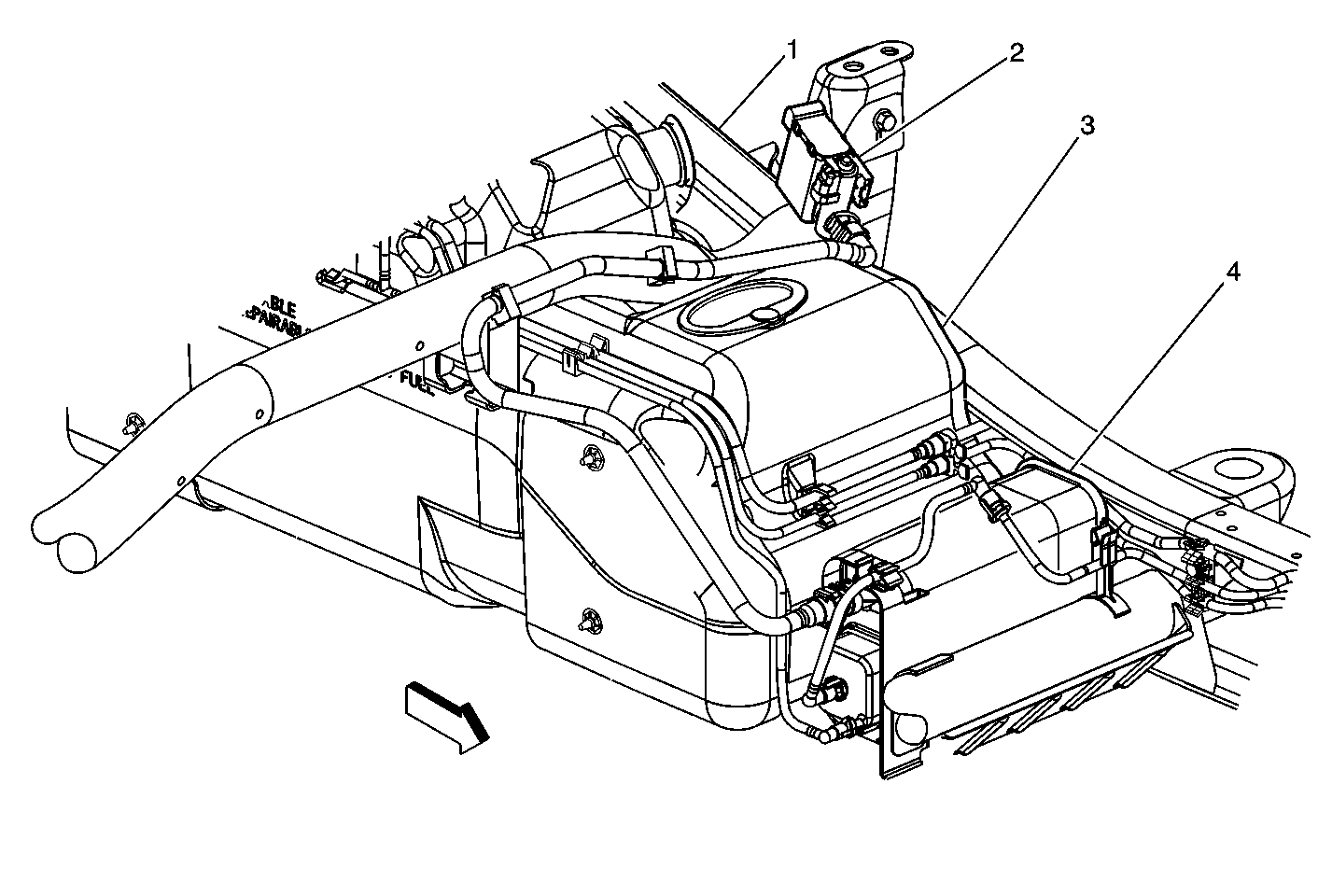
| Figure 16: |
Evaporative Emission (EVAP) Canister Vent Solenoid
|
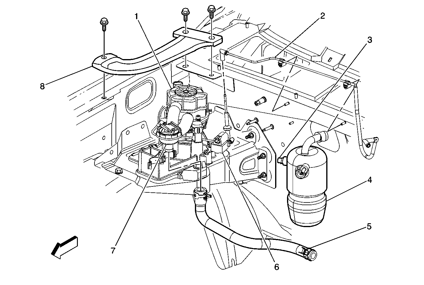
| Figure 17: |
AIR System (RPO NC1 only), AC Accumulator
|
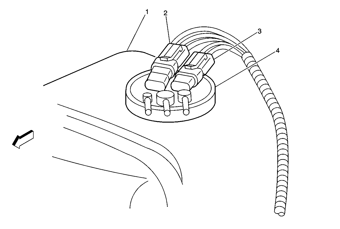
| Figure 18: |
Fuel Tank Pressure (FTP) Sensor and Fuel Pump and Sender Assembly
|