| Table 1: | Front Axle Actuator |
| Table 2: | Transfer Case Shift Control Module - C1 |
| Table 3: | Transfer Case Shift Control Module - C2 |
| Table 4: | Transfer Case Shift Control Switch - C1 |
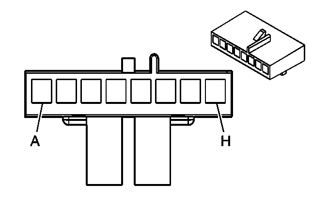
| Table 5: | Transfer Case Shift Control Switch - C2 |
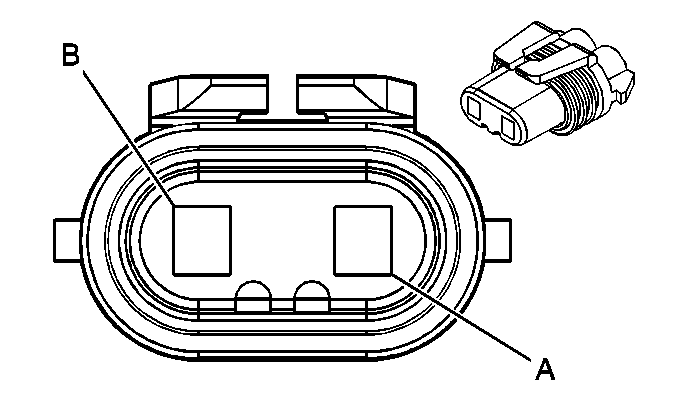
| Table 6: | Transfer Case Encoder Motor - C1 |
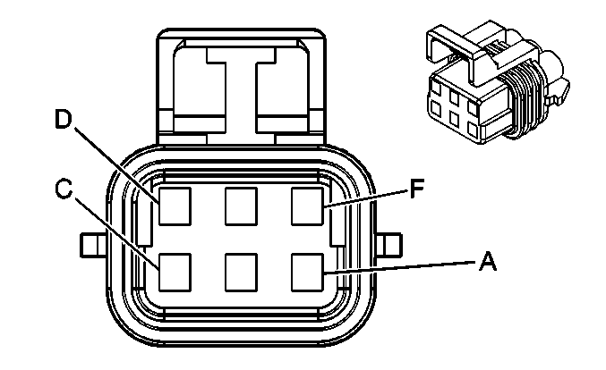
| Table 7: | Transfer Case Encoder Motor - C2 |
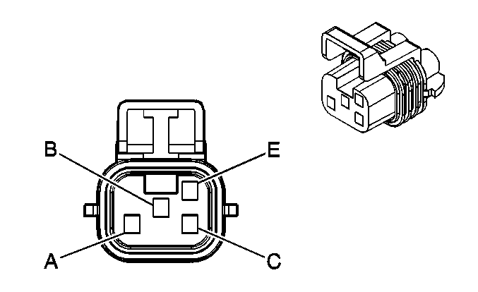
| |||||||
|---|---|---|---|---|---|---|---|
Connector Part Information |
| ||||||
Pin | Wire Color | Circuit No. | Function | ||||
A | BLK/WHT | 1695 | Axle Switch Signal | ||||
B | LT BLU | 1296 | Axle Actuator - Control | ||||
C | BRN | 241 | Ignition 3 Voltage | ||||
E | BLK | 2150 | Ground | ||||
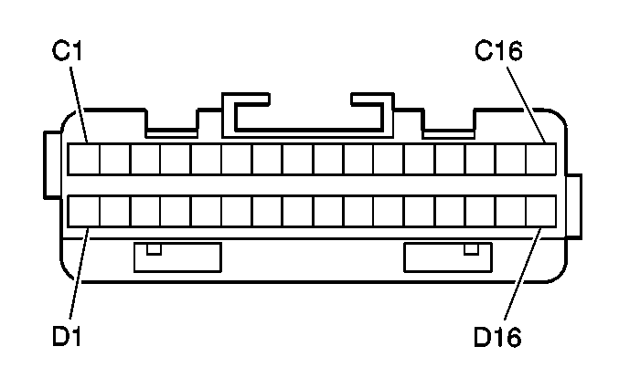
| |||||||
|---|---|---|---|---|---|---|---|
Connector Part Information |
| ||||||
Pin | Wire Color | Circuit No. | Function | ||||
C1-C3 | -- | -- | Not Used | ||||
C4 | LT GRN/BLK | 1563 | 2 'HI' Indicator - Control | ||||
C5 | BRN/WHT | 1555 | Channel P Encoder - Signal | ||||
C6 | RED/WHT | 1556 | Channel C Encoder - Signal | ||||
C7 | YEL/BLK | 1558 | Channel B Encoder - Signal | ||||
C8 | DK BLU/WHT | 1557 | Channel A Encoder - Signal | ||||
C9 | DK GRN/WHT | 1133 | ATC Class 2 Serial Data | ||||
C10 | BRN | 241 | Ignition 3 Voltage | ||||
C11-C13 | -- | -- | Not Used | ||||
C14 | BLK/WHT | 1695 | Axle Switch Signal | ||||
C15 | -- | -- | Not Used | ||||
C16 | BLK | 1850 | Ground | ||||
D1 | PPL/WHT | 1565 | 4 'LO' Indicator - Control | ||||
D2 | TAN/BLK | 1566 | 4 'HI' Indicator - Control | ||||
D3 | BRN | 1560 | Neutral Indicator Control | ||||
D4 | LT BLU | 1296 | Axle Actuator - Control | ||||
D5-D6 | -- | -- | Not Used | ||||
D7 | GRY/BLK | 1694 | 4WD Low Signal | ||||
D8-D11 | -- | -- | Not Used | ||||
D12 | BLK/WHT | 1554 | Encoder Signal Ground | ||||
D13 | LT GRN/BLK | 431 | 8 Volt Reference | ||||
D14 | LT GRN/BLK | 431 | 8 Volt Reference | ||||
D15 | -- | -- | Not Used | ||||
D16 | LT BLU | 1693 | Switch Signal | ||||
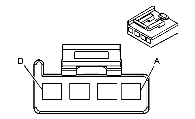
| |||||||
|---|---|---|---|---|---|---|---|
Connector Part Information |
| ||||||
Pin | Wire Color | Circuit No. | Function | ||||
A | BLK | 1552 | Motor Control A | ||||
B | RED | 1553 | Motor Control B | ||||
C | BLK | 2150 | Ground | ||||
D | ORN | 1640 | Battery Positive Voltage | ||||
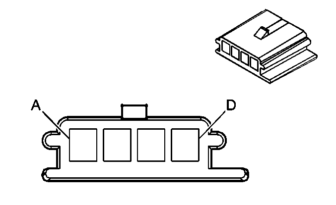
| |||||||
|---|---|---|---|---|---|---|---|
Connector Part Information |
| ||||||
Pin | Wire Color | Circuit No. | Function | ||||
A | LT GRN/BLK | 431 | 8 Volt Reference | ||||
B | LT GRN/BLK | 1563 | 2 'HI' Indicator - Control | ||||
C | TAN/BLK | 1566 | 4 'HI' Indicator - Control | ||||
D | PPL/WHT | 1565 | 4 'LO' Indicator - Control | ||||
| |||||||
|---|---|---|---|---|---|---|---|
Connector Part Information |
| ||||||
Pin | Wire Color | Circuit No. | Function | ||||
A | BLK | 1850 | Ground | ||||
B | -- | -- | Not Used | ||||
C | BRN | 1560 | Neutral Indicator Control | ||||
D | -- | -- | Not Used | ||||
E | PPL/WHT | 1382 | LED Dimming Signal | ||||
F | GRY | 8 | Instrument Panel Lamp Supply Voltage | ||||
G | PNK | 39 | Ignition 1 Voltage | ||||
H | LT BLU | 1693 | Switch Signal | ||||
| |||||||
|---|---|---|---|---|---|---|---|
Connector Part Information |
| ||||||
Pin | Wire Color | Circuit No. | Function | ||||
A | BLK | 1552 | Motor Control A | ||||
B | RED | 1553 | Motor Control B | ||||
| |||||||
|---|---|---|---|---|---|---|---|
Connector Part Information |
| ||||||
Pin | Wire Color | Circuit No. | Function | ||||
A | BLK/WHT | 1554 | Encoder Signal Ground | ||||
B | DK BLU/WHT | 1557 | Channel A Encoder - Signal | ||||
C | RED/WHT | 1556 | Channel C Encoder - Signal | ||||
D | YEL/BLK | 1558 | Channel B Encoder - Signal | ||||
E | LT GRN/BLK | 431 | 8 Volt Reference | ||||
F | BRN/WHT | 1555 | Channel P Encoder - Signal | ||||
