Air Conditioning Clutch Coil Installation Denso
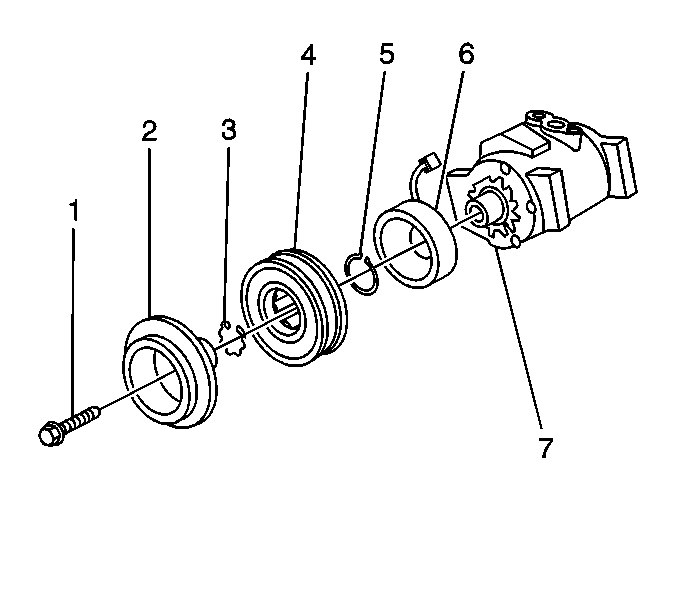
- Install the coil assembly
to the compressor.
- Install the coil snap ring.
Notice: Use the correct fastener in the correct location. Replacement fasteners
must be the correct part number for that application. Fasteners requiring
replacement or fasteners requiring the use of thread locking compound or sealant
are identified in the service procedure. Do not use paints, lubricants, or
corrosion inhibitors on fasteners or fastener joint surfaces unless specified.
These coatings affect fastener torque and joint clamping force and may damage
the fastener. Use the correct tightening sequence and specifications when
installing fasteners in order to avoid damage to parts and systems.
- Install the coil
connector retaining bracket screw.
Tighten
Tighten the screw to 9 N·m (80 lb in).
- Install the clutch hub/bearing assembly.
- Install the clutch hub/bearing snap ring.
- Install the clutch plate assembly.
- Install the clutch plate retaining bolt (1).
Tighten
Tighten the bolt to 18 N·m (13 lb ft).
Air Conditioning Clutch Coil Installation HT6/HD6/HU6
Tools Required
| • | J 33024 Clutch Coil Installer
Adapter |
| • | J 34992 Compressor Holding
Fixture |
| • | J 33017 Pulley and Bearing
Assembly Installer |
| • | J 6083 External Snap Ring
Pliers |
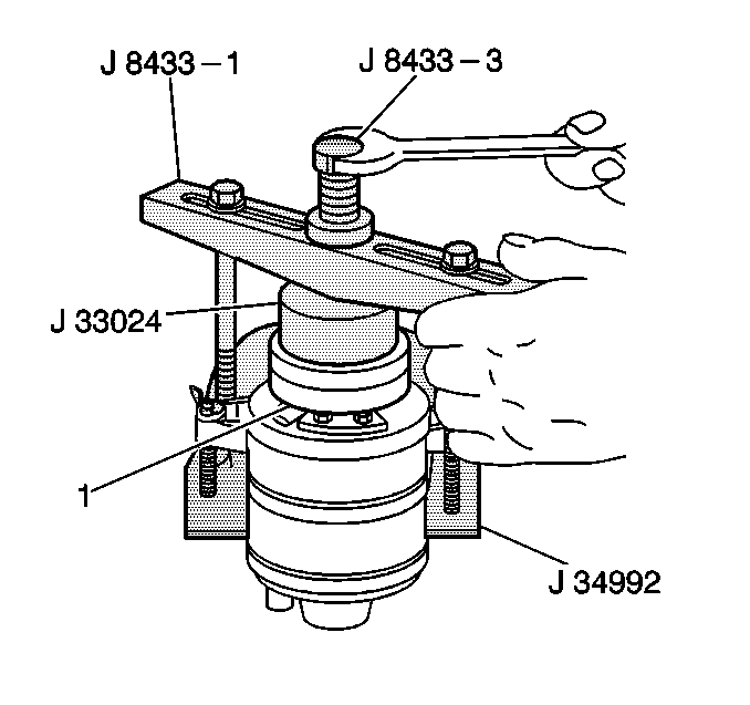
- Place the clutch coil assembly (1)
on the front head. Position the terminals at the marked location.
- Place the J 33024
over the
internal opening of the clutch coil housing.
- Align the J 33024
with the
compressor front head.
- Center the J 8433-1
in the
counter-sunk center hole of the J 33024
.
- Install the 2 through bolts and washers through the crossbar slots.
- Thread the bolts into the J 34992
in
order to achieve full fixture thickness.
- Turn the center forcing screw of the J 8433-1
in
order to force the clutch coil onto the front head. Ensure that the clutch
coil and the J 33024
remain aligned during
installation.
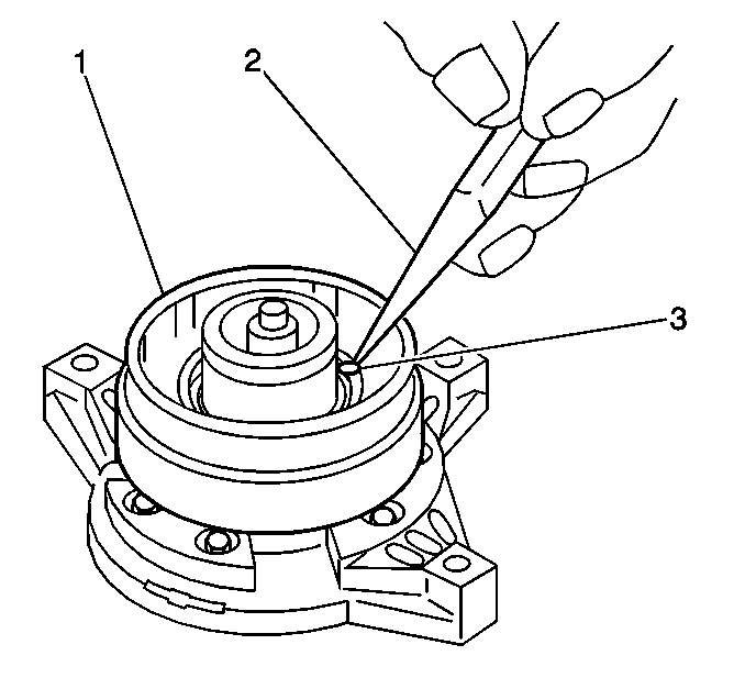
- When the coil is fully seated on the
front head, use a 1/8 inch diameter drift punch (2) in order
to stake the front head at 3 places 120 degrees apart (3),
in order to ensure that the clutch coil (1) remains in position.
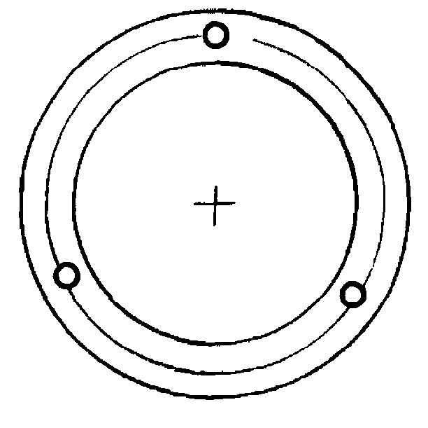
- Ensure that the stake size is only one-half
the area of the punch tip. Ensure that the stake is only approximately
0.28-0.35 mm (0.010-0.015 in) deep.
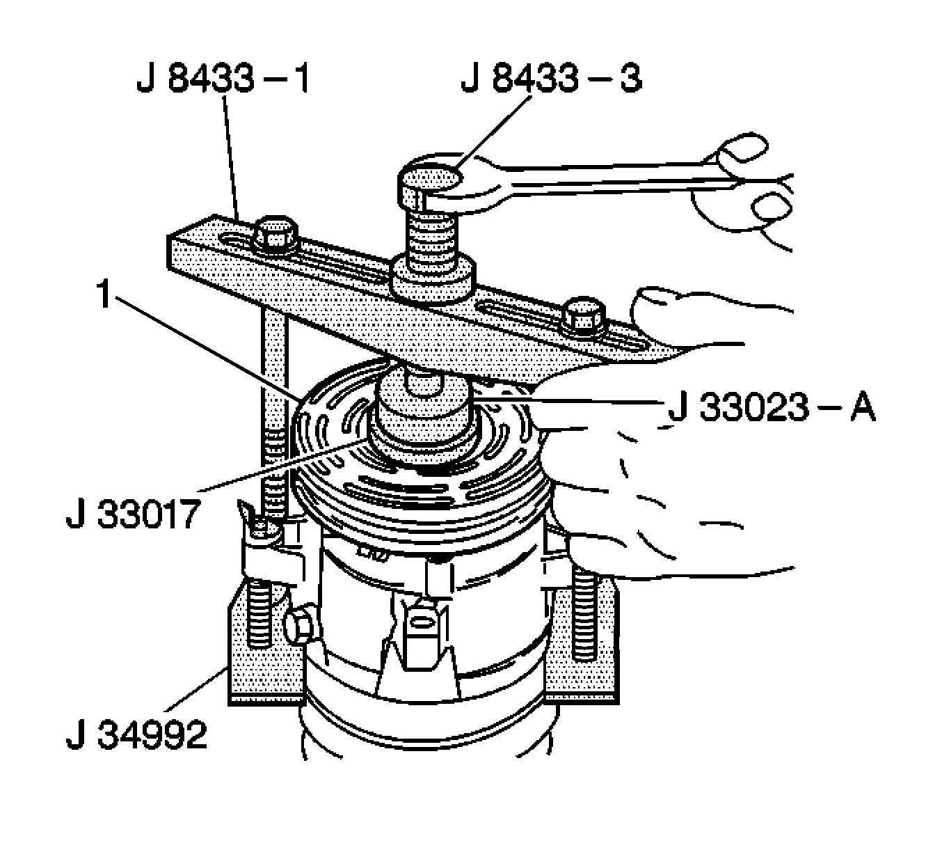
- With the compressor mounted to the J 34992
, position the pulley rotor (1)
and bearing assembly on the front head.
- Position the J 33017
and the J 33023-A
directly over the inner race of the bearing.
- Position the J 8433-1
on
the J 33023-A
.
- Assemble the 2 through bolts and washers through the puller bar
slots.
- Thread the bolts into the J 34992
.
Ensure that the thread of the through bolts engages the full thickness of
the J 34992
.
- Tighten the center screw in the J 8433-1
in
order to force the pulley rotor and bearing assembly onto the compressor front
head.
If the J 33017
slips off direct
in-line contact with the inner race and bearing, perform the following
steps:
| 15.2. | Realign the installer and the pilot in order to ensure that the J 33017
properly clears the front head. |
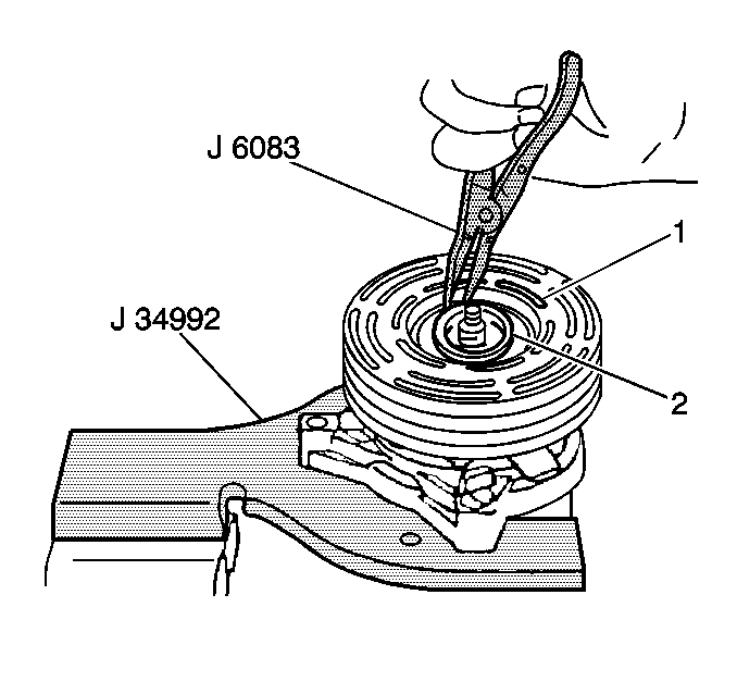
- Use the J 6083
in order to install the following components:
- Install the clutch plate and hub assembly. Refer to
Compressor Clutch Plate/Hub Assembly Replacement
.


