Circuit Description
The steering wheel position sensor inputs to the rear wheel steering control module consists of 3 digital input circuits, phase A, phase B, and index marker pulse and 1 analog signal circuit. The steering wheel position sensor supply voltage is between 4.9-5.1 volts.
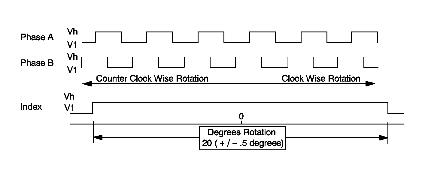
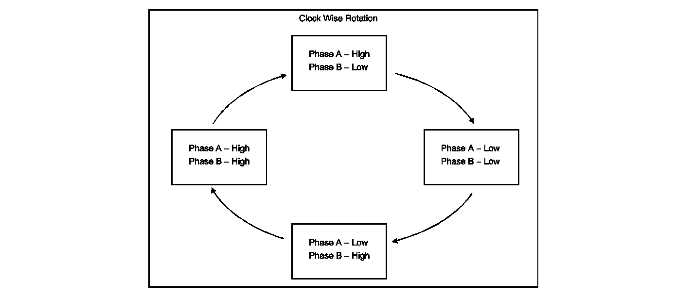
Phase A and phase B circuits are digital pulse signals whose output represents one degree of steering wheel rotation. When observing the phase A data and the phase B data parameters on the scan tool, the parameters will not have the same value at the same time. When the steering wheel is rotated, the phase A data and the phase B data parameters will be shown as high or low on the scan tool.
The marker pulse is a digital pulse that is displayed as high on the scan tool for 20 ° only when the steering wheel angle is between -10 and +10 °.
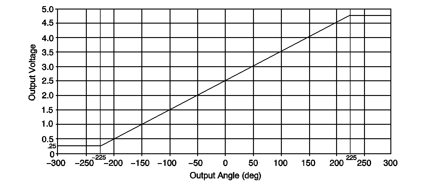
Steering wheel position sensor, analog signal, voltage is at or near 2.5 volts with the wheels at center voltage increases/decreases for less than 1 full turn (+/- 225°) then plateaus for remainder of wheel travel.
Conditions for running the DTC
Turn ON the ignition, with engine ON.
Conditions for Setting the DTC
| • | The marker pulse data parameter is high for less than 20 ° of the steering wheel angle. |
| • | The marker pulse data parameter is high for greater than 20 ° of the steering wheel angle. |
| • | The marker pulse data parameter is high when the steering wheel angle parameter is greater than +90 °. |
| • | The marker pulse data parameter is high when the steering wheel angle parameter is less than -90 degrees. |
| • | The steering wheel sensor analog output voltage is less than 0.125 volts. |
| • | The steering wheel sensor analog output voltage is greater than 4.875 volts. |
| • | The steering wheel position sensor phase A circuit is shorted to ground, open or shorted to voltage. |
| • | The steering wheel position sensor phase B circuit is shorted to ground, open or shorted to voltage. |
Action Taken When the DTC Sets
| • | The Service 4 Wheel Steer indicator in IPC will be displayed. |
| • | The code is displayed on the scan tool as DTC C0455. |
| • | The output to the motor is ramped down slowly, at a rate of 2 ° per second to 0 ° and held. |
| • | The rear wheels will be returned to the centered position. |
Conditions for Clearing the DTC
| • | Conditions for DTC are not currently present. |
| • | The module receives a clear code command from the scan tool. |
| • | The DTC clears after 100 malfunction free ignition cycles. |
Diagnostic Aids
The following conditions are possible causes:
| • | The steering wheel was rotated with the steering gear disconnected. |
| • | A malfunctioning steering wheel position sensor is present. |
| • | A steering wheel position sensor circuit is open. |
| • | A steering wheel position sensor circuit was shorted. |
Perform an inspection of the wiring and of the connectors. Failure to carefully inspect the wiring and the connectors may result in misdiagnosis. Misdiagnosis causes part replacement with reappearance of the malfunction.
Steering Wheel Position Sensor -- Digital Signal
| • | 3 outputs used (Phase A, Phase B, Index Pulse) |
| • | Phase A & Phase B |
| Offset PWM wave forms created when turning the wheel |
| • | Index pulse |
| Signal is present only when steering wheel is within 10 degrees either side of center |
Output is used to determine Direction of Rotation and Rate of Rotation
Steering Wheel Position Sensor--Digital Signal

Steering Wheel Position Sensor--A and B Phase

Steering Wheel Position Sensor - Analog Signal

Test Description
The numbers below refer to the step numbers on the diagnostic table.
-
This step will help determine if the 5 volt reference circuit is open.
-
This step will help determine if the sensor return circuit is open.
-
Test for the proper operation of the phase A circuit.
-
Test for the proper operation of the phase B circuit.
-
Test for the proper operation of the marker pulse circuit.
-
Test for the proper operation of the sensor signal circuit.
-
Test for a short to ground in the 5 volt reference circuit.
Step | Action | Values | Yes | No |
|---|---|---|---|---|
Schematic Reference: Rear Wheel Steering Schematics Connector End View Reference: Rear Wheel Steering Connector End Views | ||||
1 | Did you perform the Diagnostic System Check--Rear Wheel Steering? | Go to Step 2 | ||
2 |
Do all of the parameters change? | Go to Diagnostic Aids | Go to Step 3 | |
Does the scan tool indicate that phase A, the phase B , marker pulse data parameter are all high and the sensor signal data parameter equals 5 volts? | Go to Step 14 | Go to Step 4 | ||
Does the scan tool indicate that phase A, the phase B, marker pulse data parameter are all low and the sensor signal data parameter equals 0 volt? | Go to Step 13 | Go to Step 5 | ||
With a scan tool, observe the phase A parameter, while turning the steering wheel. Does the phase A data parameter change state? | high/low | Go to Step 7 | Go to Step 6 | |
6 | Does the scan tool indicate that the phase A data parameter is high? | Go to Step 18 | Go to Step 17 | |
With a scan tool, observe the phase B parameter, while turning the steering wheel. Does the phase B data parameter change state? | high/low | Go to Step 9 | Go to Step 8 | |
8 | Does the scan tool indicate that the phase B data parameter is high? | Go to Step 18 | Go to Step 17 | |
With a scan tool, observe the marker pulse data parameter while turning the steering wheel. Does the marker pulse data parameter change state? | high/low | Go to Step 11 | Go to Step 10 | |
10 | Does the scan tool indicate that the marker pulse data parameter is high? | Go to Step 18 | Go to Step 17 | |
With a scan tool, observe the sensor signal data parameter, while turning the steering wheel. Is the voltage of the sensor signal data parameter greater than the specified value? | 4.875 V | Go to Step 18 | Go to Step 12 | |
12 | Is the voltage of the sensor signal data parameter less than the specified value? | 0.125 V | Go to Step 17 | Go to Step 13 |
13 |
Does the scan tool indicate that the sensor signal data parameter is greater than the specified value? | 4.875 V | Go to Step 19 | Go to Step 20 |
Does the scan tool indicate that the sensor signal data parameter is less than the specified value? | 0.125 V | Go to Step 16 | Go to Step 15 | |
15 | Test the steering wheel position sensor 5 volt reference circuit for a short to ground. Refer to Circuit Testing and Wiring Repairs in Wiring Systems. Did you find and correct the condition? | Go to Step 25 | Go to Step 17 | |
16 | Test the steering wheel position sensor 5 volt reference circuit for an open or a short to voltage. Refer to Circuit Testing and Wiring Repairs in Wiring Systems. Did you find and correct the condition? | Go to Step 25 | Go to Step 22 | |
17 | Test the steering wheel position sensor phase A, phase B, marker pulse, or sensor signal circuit for a short to ground. Refer to Circuit Testing and Wiring Repairs in Wiring Systems. Did you find and correct the condition? | Go to Step 25 | Go to Step 21 | |
18 | Test the steering wheel position sensor phase A, phase B, marker pulse, or sensor signal circuit for an open or short to voltage. Refer to Circuit Testing and Wiring Repairs in Wiring Systems. Did you find and correct the condition? | Go to Step 25 | Go to Step 21 | |
19 | Test the steering wheel position sensor return circuit for a short to voltage. Refer to Circuit Testing and Wiring Repairs in Wiring Systems. Did you find and correct the condition? | Go to Step 25 | Go to Step 22 | |
20 | Test the steering wheel position sensor return circuit for an open or high resistance. Refer to Circuit Testing and Wiring Repairs in Wiring Systems. Did you find and correct the condition? | Go to Step 25 | Go to Step 22 | |
21 | Inspect for poor connections at the harness connector of the steering wheel position sensor connector. Refer to Testing for Intermittent Conditions and Poor Connections and Connector Repairs in Wiring Systems. Did you find and correct the condition? | Go to Step 25 | Go to Step 23 | |
22 | Inspect for poor connections at the harness connector of the rear wheel steering control module connector. Refer to Testing for Intermittent Conditions and Poor Connections and Connector Repairs in Wiring Systems.
Did you find and correct the condition? | Go to Step 25 | Go to Step 24 | |
23 |
Important: Perform the Learn Alignment procedure. Refer to Wheel Alignment Measurement in Wheel Alignment Replace the steering wheel position sensor. Refer to Steering Wheel Position Sensor or Steering Shaft Lower Bearing Replacement in Steering Wheel and Column. Is the replacement complete? | Go to Step 25 | ||
24 |
Important: Perform the Learn Alignment procedure. Refer to Wheel Alignment Measurement in Wheel Alignment Replace the rear wheel steering module. Refer to Rear Wheel Steering Control Module Replacement Did you complete the replacement? | Go to Step 25 | ||
25 |
Does the DTC reset? | -- | Go to Step 2 | System OK |
