Pinion Depth Adjustment 8.6 Inch, 9.5 Inch, 11.5 Inch Axles
Tools Required
| • | J 45108 Pinion Setting
Gage Block (9.5 inch axle) |
| • | J 21777-86 Side Bearing Disc (2 Required) (9.5 inch axle) |
| • | J 34925 Pinion Setting
Gauge Kit (8.6 inch, 9.5 inch axle, 11.5 inch axle) |
| • | J 44416 Pinion Setting
Adapter Kit (11.5 inch axle) |
Important: Make sure all of the tools, the differential side bearing bores, and the pinion
bearing cups are clean before proceeding.
- Lubricate the pinion bearings with axle lubricant. Refer to
Fluid and Lubricant Recommendations
in Maintenance and Lubrication.
- Install the pinion bearings into the axle housing.
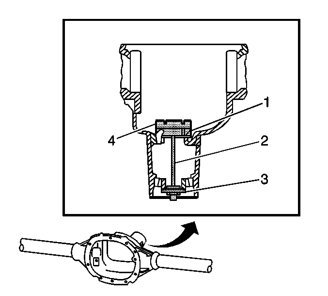
- Assemble
the following components into the axle housing:
| • | For the 8.6 in axle, assemble the J 21777-35 (1),
the J 21777-43 (2), the J 21777-42 (3),
and the J 21777-29 (4) as shown. |
| • | For the 9.5 in axle, assemble the J 21777-8 (1),
the J 21777-43 (2), the J 21777-42 (3),
and the J 45108
(4)
as shown. |
| • | For the 11.5 in axle, assemble the J 44416-3 (1,4),
the J 21777-43 (2), and the J 44416-2 (3)
as shown. |
- While holding the J 21777-43 stationary, install an inch-pound
torque wrench on the nut of the J 21777-43 and tighten the nut
until a rotating torque of 2.2 N·m (20 lb in)
is obtained.
Rotate the assembly several times in both directions in order to seat the
pinion bearings.
- Check the rotating torque of the assembly. If the torque is less than
1.7 N·m (15 lb in), tighten the nut on the J 21777-43
until a rotating torque of 1.7-2.8 N·m (15-25 lb in)
is obtained.
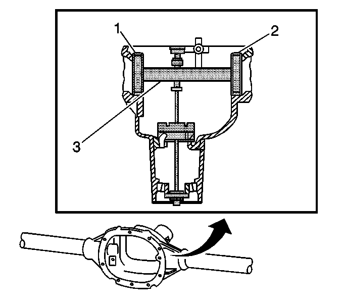
- Assemble
the following components into the differential carrier bore of the axle housing:
| • | For the 8.6 in axle, assemble the J 21777-45 (1, 2)
to the J 21777-1 (3) as shown. |
| • | For the 9.5 in axle, assemble the J 21777-86 (1, 2)
to the J 21777-1 (3) as shown. |
| • | For the 11.5 in axle, assemble the J 44416-1 (1, 2)
to the J 21777-1 (3) as shown. |
- Install the bearing caps.
Notice: Use the correct fastener in the correct location. Replacement fasteners
must be the correct part number for that application. Fasteners requiring
replacement or fasteners requiring the use of thread locking compound or sealant
are identified in the service procedure. Do not use paints, lubricants, or
corrosion inhibitors on fasteners or fastener joint surfaces unless specified.
These coatings affect fastener torque and joint clamping force and may damage
the fastener. Use the correct tightening sequence and specifications when
installing fasteners in order to avoid damage to parts and systems.
- Install the bearing cap bolts.
Tighten
Tighten the bearing cap bolts to 75 N·m (55 lb ft).
- Rotate the J 21777-1 within the J 21777-45
(8.6 in axle), or the J 21777-86 (9.5 in axle), or the
J 44416-1 (11.5 in axle). The J 21777-1
must rotate back and forth freely within the discs. If the J 21777-1
does not rotate freely, disassemble the components, inspect for proper
seating and/or mis-aligned components and re-assemble.
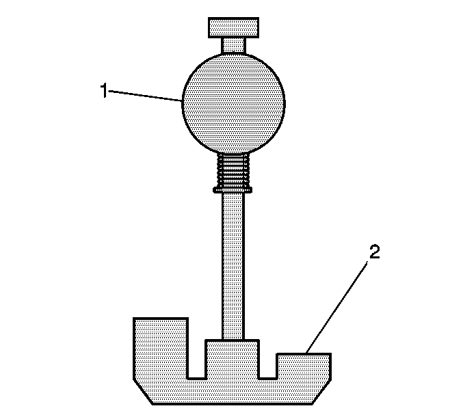
- Align the plunger of the J 21777-1
(1) to the 8.5 in gauge block setting of the J 21777-29
(8.6 in axle), or the J 45108
(9.5 in axle), or the J 44416-3 (11.5 in
axle) (2).
- Install the J 8001
to
the J 21777-1 as follows:
| 11.1. | Loosely clamp the J 8001
onto the stem on the J 21777-1. |
| 11.2. | Place the contact pad of the J 8001
onto the mounting post of the J 21777-1. |
| 11.3. | With the contact pad of the J 8001
touching the mounting post of the J 21777-1, loosen the
lock nut on the J 8001
and push down on the J 8001
until the needle the J 8001
has
turned 3/4 of a turn clockwise. |
| 11.4. | Tighten the clamp on the J 8001
finger tight. |
- Move the plunger of the J 21777-1 back and forth until the
needle of the J 8001
indicates
the greatest deflection.
The deflection is the point where the needle changes direction.
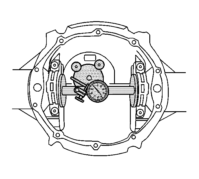
- At the greatest point of deflection, move
the housing of the J 8001
until
the needle indicates zero.
- Move the plunger of the J 21777-1 back and forth again to
verify the zero setting. Adjust the housing of the J 8001
as necessary to set the needle to zero.
- Rotate the plunger of the J 21777-1 away from the J 21777-29
(8.6 in axle), the J 45108
(9.5 in axle), or the J 44416-3 (11.5 in axle) until
it no longer touches the J 21777-29 (8.6 in axle), the J 45108
(9.5 in axle), or
the J 44416-3 (11.5 in axle).
- The value indicated on the J 8001
is the thickness of the shim needed in order to set the depth of the
pinion.
- Select the shim that indicates the proper thickness. Measure the shim
with a micrometer in order to verify that the thickness is correct.
- Remove the pinion depth setting tools.
- Remove the pinion bearings.
- Install the pinion shim between the pinion gear and the inner pinion
bearing. Refer to
Drive Pinion Bearings Replacement
.
Pinion Depth Adjustment 10.5 Inch Axle
- Install the differential, if necessary. Refer to
Differential Replacement.
Important: Measure and record the thickness of the pinion gear bearing retainer shim before any service procedures are performed to the pinion gear bearing retainer assembly.
- Install the original shim to the pinion bearing retainer. If the original shim is not available, install a 0.41 mm (0.016 in) shim to build pinion depth.
Important: Do not apply sealant to the pinion gear bearing retainer at this time.
- Install the pinion gear bearing retainer.
Notice: Refer to Fastener Notice in the Preface section.
- Install the pinion gear bearing retainer bolts.
Tighten
Tighten the pinion gear bearing retainer bolts to 88 N·m (65 lb ft).
- Adjust the backlash. Refer to
Backlash Adjustment.
- Perform a gear tooth pattern check on the pinion and the ring gear. Refer to
Gear Tooth Contact Pattern Inspection.
- If the gear tooth contact pattern indicates a high or a low flank contact pattern, adjust the pinion depth by doing the following:
| 7.1. | Remove the pinion gear bearing retainer bolts. |
| 7.2. | Remove the pinion gear bearing retainer. |
| • | If the gear tooth contact pattern shows a high flank contact pattern, install a shim one size larger. |
| • | If the gear tooth contact pattern shows a low flank contact pattern, install a shim one size smaller. |
| 7.4. | Install the new shim to the pinion gear bearing retainer. |
| 7.5. | Install pinion gear bearing retainer. |
| 7.6. | Install pinion gear bearing retainer bolts. |
Tighten
Tighten the pinion gear bearing retainer bolts to 88 N·m (65 lb ft).
| 7.8. | If the gear tooth pattern is still incorrect, adjust the shim thickness as necessary and recheck the gear tooth pattern of the pinion and the ring gear. |
- Inspect the backlash between the pinion and the ring gear and adjust, if necessary. Refer to
Backlash Adjustment.
The pinion shims are available in the following sizes:
Shim Sizes
Pinion Depth Adjustment 9.75 Inch Axle
Tools Required
| • | J 24433 Pinion Cone
and Side Bearing Installer |
| • | J 34925 Pinion Setting
Gage and Components |
| • | J 45692 Pinion Shim
Selector Kit - Dana Axles |
| • | J 45710 Pinion Bearing
Oil Seal Installer |
Important:
| • | Make sure all of the tools, the differential side bearing bores, and
the pinion bearing cups are clean before proceeding. |
| • | The pinion position shim may be located between the oil deflector and
the axle housing. If the pinion position shim is located between the oil baffle and
the axle housing, the shim must be removed before the pinion depth measuring procedure
can be performed. |
- Remove the drive pinion, if necessary. Refer to
Drive Pinion and Ring Gear Replacement
.
- Remove the inner pinion bearing, if necessary. Refer to
Drive Pinion Bearings Replacement
.
- Inspect the axle housing for a pinion position shim between the inner
pinion bearing cup or the oil baffle and the axle housing.
- If a shim is present, remove the oil baffle, the pinion position shim,
and the inner pinion bearing cup. Refer to
Drive Pinion Bearings Replacement
.
- Install the inner pinion bearing cup, if removed. Do not install the oil
baffle or the pinion position shim at this time. Refer to
Drive Pinion Bearings Replacement
.
- Lubricate the pinion bearings with axle lubricant. Refer to
Fluid and Lubricant Recommendations
in Maintenance and
Lubrication.
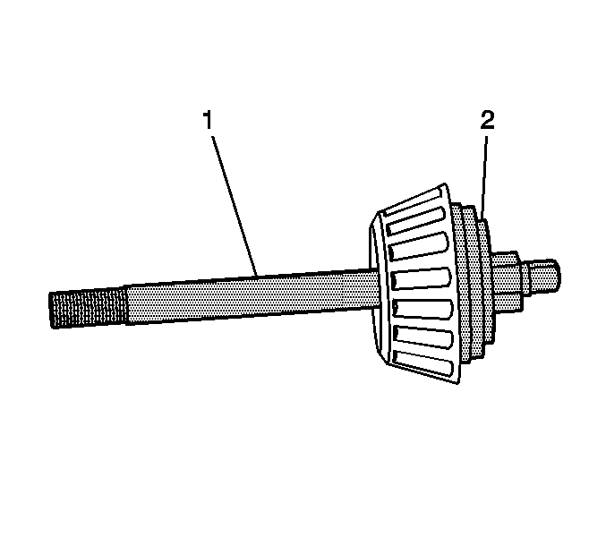
- Assemble
the J 45692-5 (2) and the outer pinion bearing onto the J 21777-43 (1)
as shown.
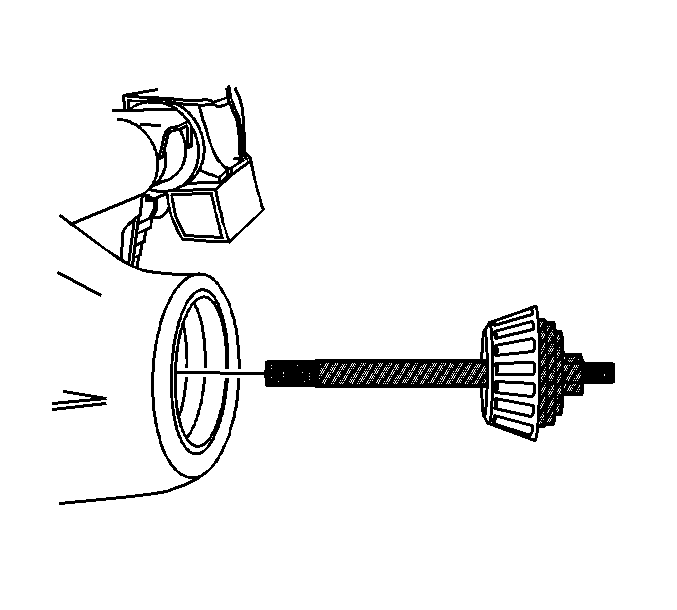
- Install the J 45692-5, the outer pinion bearing, and the J 21777-43
into the axle housing.
- Install the inner pinion bearing into the axle housing.
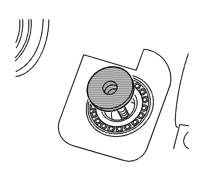
- Install
the J 21777-35 into the inner pinion bearing as shown.
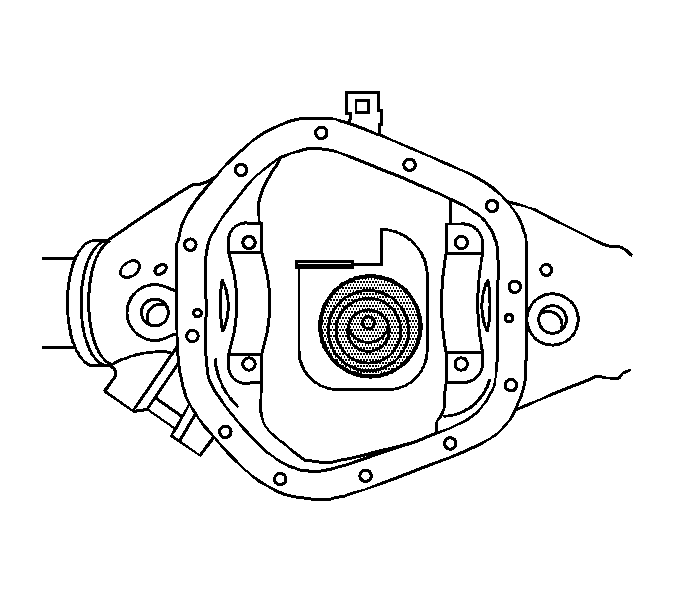
- Install the J 45692-1 into the axle
housing as shown.
- While holding the J 21777-43 stationary, tighten the nut on the
J 21777-43 just until the end play between the pinion bearings is removed.
- Rotate the assembly several times in both directions in order to seat
the pinion bearings.
- Measure the rotating torque of the assembly using an inch-pound torque
wrench.
Specification
The rotating torque of the assembly should be between 2.3-5.1 N·m
(20-45 lb in).
- If the rotating torque of the assembly is less than 2.3 N·m
(20 lb in), continue to tighten the nut of the J 21777-43 until
a rotating torque of 2.3-5.1 N·m (20-45 lb in)
is obtained.
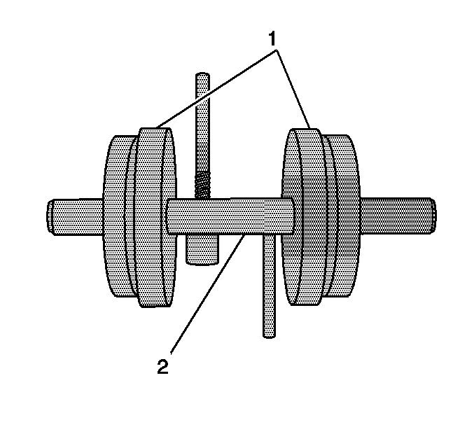
- Assemble the J 45692-2 (1) and the J 21777-1 (2)
as shown.
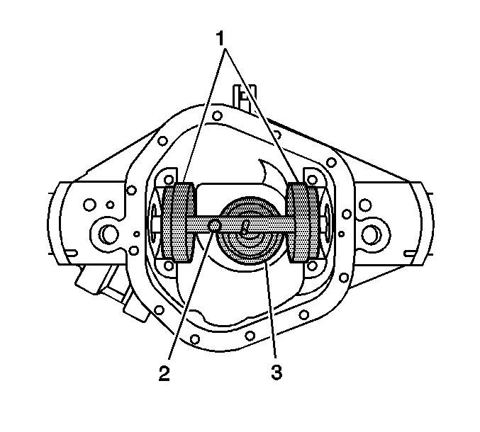
- Install
the J 45692-2 (1) and the J 21777-1 (2) into the axle
housing. Place the stem of the J 21777-1 onto the bottom step of the J 45692-1.
Notice: Refer to Fastener Notice in the Preface section.
Important: Corresponding letters are stamped on the bearing caps and axle housing. The
bearing caps must be reassembled in the same position as removed.
- Install the bearing caps and bearing cap bolts.
Tighten
Tighten the bearing cap bolts to 75 N·m (55 lb ft).
- Rotate the J 21777-1 within the J 45692-2. The J 21777-1
must rotate back and forth freely with the discs. If the J 21777-1 does not
rotate freely, disassemble the components, inspect for proper seating and/or mis-aligned
components and re-assemble.
- Install the J 8001
to
the J 21777-1 as follows:
| 20.1. | Loosely clamp the J 8001
onto the stem on the J 21777-1. |
| 20.2. | Place the contact pad of the J 8001
onto the mounting post of the J 21777-1. |
| 20.3. | With the contact pad of the J 8001
touching the mounting post of the J 21777-1, loosen the lock
nut on the J 8001
and push down
on the J 8001
until the needle the J 8001
has turned 3/4 of a turn clockwise. |
| 20.4. | Tighten the clamp on the J 8001
finger tight. |
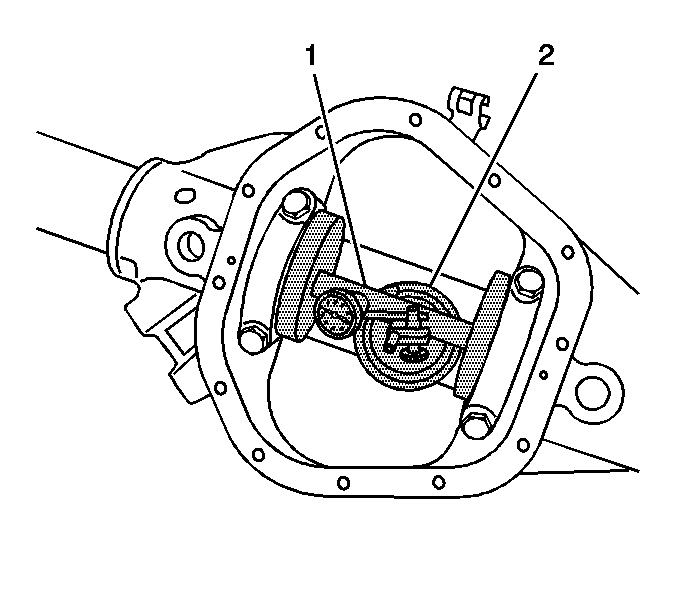
- Move the plunger of the J 21777-1 (1)
back and forth on the bottom step of the J 45692-1 (2) until the needle
of the J 8001
indicates the greatest
deflection.
The deflection is the point where the needle changes direction.
- At the greatest point of deflection, move the indicator housing of theJ 8001
until the needle indicates ZERO.
- Move the plunger of the J 21777-1 back and forth again to verify
the ZERO setting. Adjust the housing of the J 8001
as necessary to set the needle to ZERO.
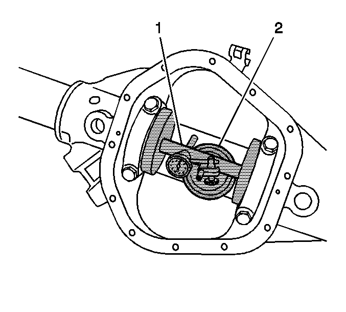
- Rotate the plunger of the J 21777-1 (1) away from the J 45692-1 (2).
The value indicated is the amount of pinion position shim thickness required
for a nominal pinion setting.
- If the oil baffle was removed, measure the thickness of the new oil baffle
with a micrometer. Subtract this measurement from the thickness determined in step
23.
- In order to adjust the thickness of the service pinion position shim for
the drive pinion that is to be installed, do the following:
| 26.1. | Read the number on the button end of the pinion. |
If the number on the button end of the pinion is "0", no adjustment
of the pinion preload shim pack is necessary.
| 26.2. | If the number is not "0", the number will also have a corresponding
"+" or "-" in front of it. |
The "+" or "-" indicates the amount of pinion position
shim thickness that either needs to be added to or subtracted from the amount determined
in step 24 in order to the drive pinion gear to be positioned properly within the
axle housing.
| • | For example, if the number on the button end of the pinion is a "+3",
this indicates that 0.0762 mm (0.003 in) of shim thickness will need
to be subtracted from the value determined in step 24 in order to place the teeth
of the pinion in the best running position with the teeth of the ring gear. Refer
to the table. |
| • | If the number on the button end of the pinion is a "-3",
this indicates that 0.0762 mm (0.003 in) of shim thickness will need
to be added to the value determined in step 24 in order to place the teeth of the
pinion in the best running position with the teeth of the ring gear. Refer to the
table. |
- Remove the pinion depth setting tools.
- Remove the pinion bearings.
- Select a service pinion position shim corresponding to the thickness determined
in step 25.
Measure the thickness of the shim with a micrometer in order to verify the thickness.
- Remove the inner pinion bearing cup. Refer to
Drive Pinion Bearings Replacement
.
- Install the service pinion position shim, the new oil baffle, and the
inner pinion bearing cup into the axle housing. Refer to
Drive Pinion Bearings Replacement
.
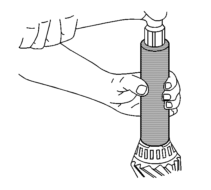
- Install the inner pinion bearing onto the
drive pinion using the J 24433
.
- Install the original pinion preload shims onto the drive pinion. If the
original shims are not available, assemble 1.52 mm (0.060 in) of pinion
preload shims to install.
Measure each shim separately with a micrometer and add the thickness together
to determine the total shim pack size.
- Install the drive pinion with the inner pinion bearing and the pinion
preload shims into the axle housing.
- Install the outer pinion bearing.
- Install the thrust washer.
- Seat the pinion yoke onto the pinion shaft by tapping it with a soft-faced
hammer until a few pinion shaft threads show through the yoke.
- Install the pinion yoke nut washer.
- Install the pinion yoke nut.
Tighten
Tighten the pinion yoke nut to 252 N·m (186 lb ft).
- Measure the rotating torque of the drive pinion using an inch-pound torque
wrench.
Specification
The rotating torque of the drive pinion should be between 2.3-5.1 N·m
(20-45 lb in).
- If the rotating torque of the drive pinion is not within specifications,
adjust the pinion preload shim thickness by doing the following:
| 41.1. | Install the J 8614-01
to the pinion yoke. |
| 41.2. | Remove the pinion nut while holding the J 8614-01
. |
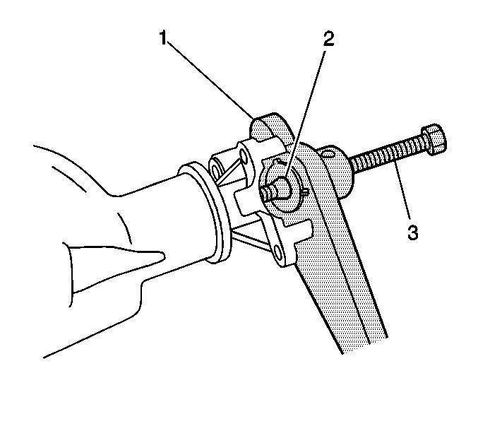
| 41.4. | Install the J 8614-2 (2) and
the J 8614-3 (3) into the J 8614-01
(1) as shown. |
| 41.5. | Remove the pinion yoke by turning the J 8614-3 (3) clockwise
while holding the J 8614-01
(1). |
| 41.6. | Remove the thrust washer. |
Ensure that the J 22536
is firmly seated on the drive pinion.
| 41.8. | Drive the pinion out using the J 22536
and a hammer. |
| 41.9. | Remove the outer pinion bearing. |
| 41.10. | Remove the pinion preload shim(s). |
| 41.11. | Adjust the amount of pinion preload shim thickness by doing the following: |
| | Important: Removing approximately 0.0254 mm (0.001 in) of shim thickness
will increase the rotating torque by approximately 71-89 N·m
(8-10 lb in).
|
| • | If the rotating torque is too low, remove the appropriate amount of shim thickness
from the shim thickness pack using the guideline above. |
| • | Measure each shim separately with a micrometer and add the thickness together
to determine the total shim pack size. |
| | Important: Adding approximately 0.0254 mm (0.001 in) of shim thickness will
decrease the rotating torque by approximately 71-89 N·m (8-10 lb in).
|
| • | If the rotating torque is too high, add the appropriate amount of shim thickness
to the shim thickness pack using the guideline above. |
| • | Measure each shim separately with a micrometer and add the thickness together
to determine the total shim pack size. |
- Install the new pinion preload shim pack onto the drive pinion.
- Install the drive pinion with the inner pinion bearing and the pinion
preload shims into the axle housing.
- Install the outer pinion bearing.
- Install the thrust washer.
- Seat the pinion yoke onto the pinion shaft by tapping it with a soft-faced
hammer until a few pinion shaft threads show through the yoke.
- Install the pinion yoke nut washer.
- Install the pinion yoke nut.
Tighten
Tighten the pinion yoke nut to 252 N·m (186 lb ft).
- Measure the rotating torque of the drive pinion using an inch-pound torque
wrench.
Specification
The rotating torque of the drive pinion should be between 2.3-5.1 N·m
(20-45 lb in).
- If the rotating torque of the drive pinion is not within specification,
adjust the pinion bearing preload shim pack as necessary following the steps above.
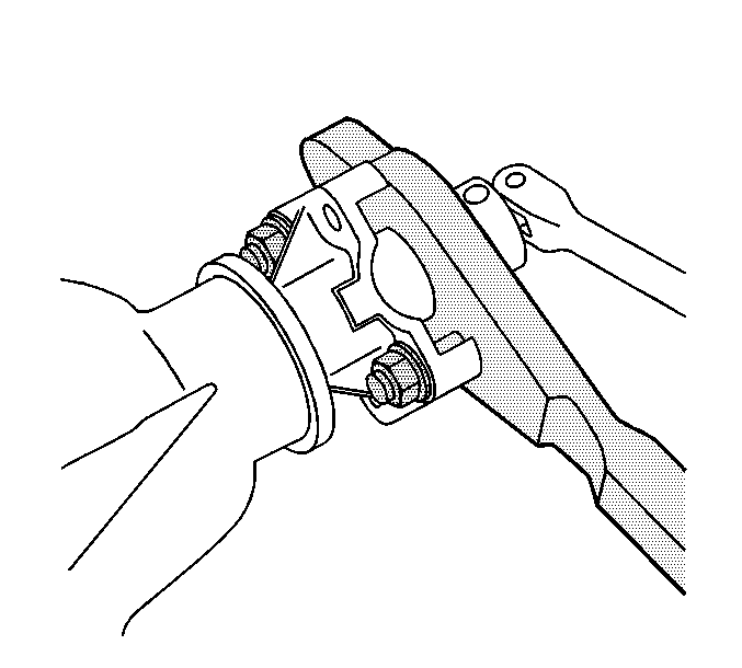
- If the rotating torque is within specifications,
install the J 8614-01
to the pinion
yoke.
- Remove the pinion nut while holding the J 8614-01
.
- Remove the washer.

- Install the J 8614-2 (2)
and the J 8614-3 (3) into the J 8614-01
(1) as shown.
- Remove the pinion yoke by turning the J 8614-3 (3) clockwise
while holding the J 8614-01
(1).
- Apply a light coat of axle lubricant, GM P/N 12378557 or
equivalent meeting GM Specification 9986207, to lip of the pinion seal.
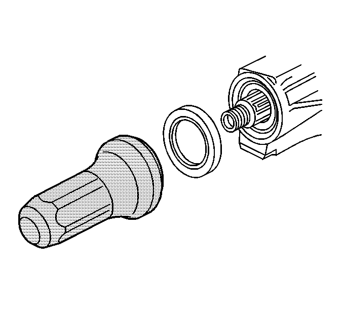
- Install the new pinion oil seal using theJ 45710
.
- Seat the pinion yoke onto the pinion shaft by tapping it with a soft-faced
hammer until a few pinion shaft threads show through the yoke.
- Install the pinion yoke nut washer.
- Install the new pinion yoke nut.
Tighten
Tighten the pinion yoke nut to 370 N·m (272 lb ft).
- Measure the rotating torque of the drive pinion using an inch-pound torque
wrench.
Specification
The rotating torque of the drive pinion should be between 2.3-5.1 N·m
(20-45 lb in).
Pinion Marking Table
Pinion Marking
| Increase/Decrease the Distance Between Ring Gear Marking And Pinion Head
| Increase/Decrease the Shim Pack Thickness
|
Positive (+)
| Must Increase
| Decrease
|
Negative (-)
| Must Decrease
| Increase
|
Zero (0)
| OK
| Use Nominal Setting
|


