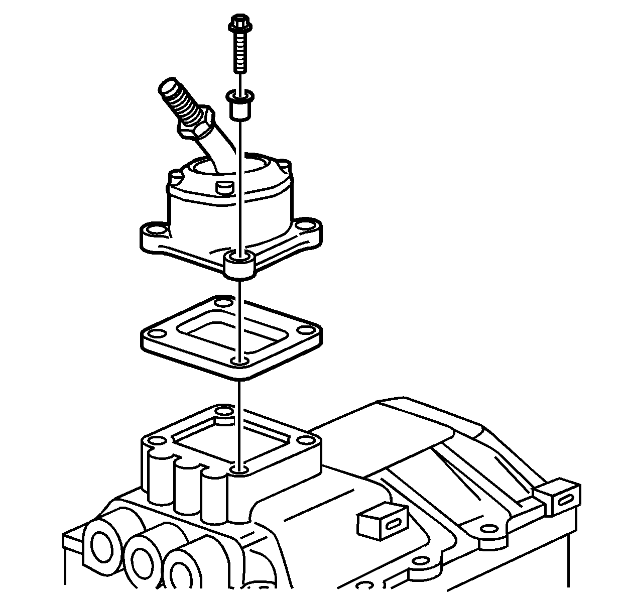
Important: In order to remove the shift tower the transmission must be in neutral.
- Shift the transmission to neutral.
- Remove the bolts that secure the shift lever to the transmission.
- Remove the shift lever and shift tower spacer.
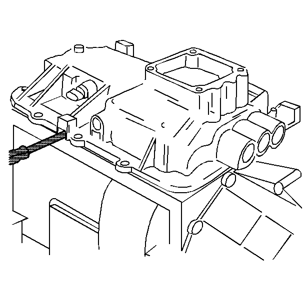
Important: Note the location of the brackets on the shift cover bolts in order
to reinstall them in the correct location.
- Remove the bolts that secure the shift cover to the transmission.
- Using screwdrivers in the transmission case slots, pry the shift
cover from the transmission.
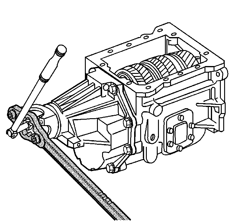
- Using the J 8614-01
to hold the propeller shaft yoke,
loosen the mainshaft nut.
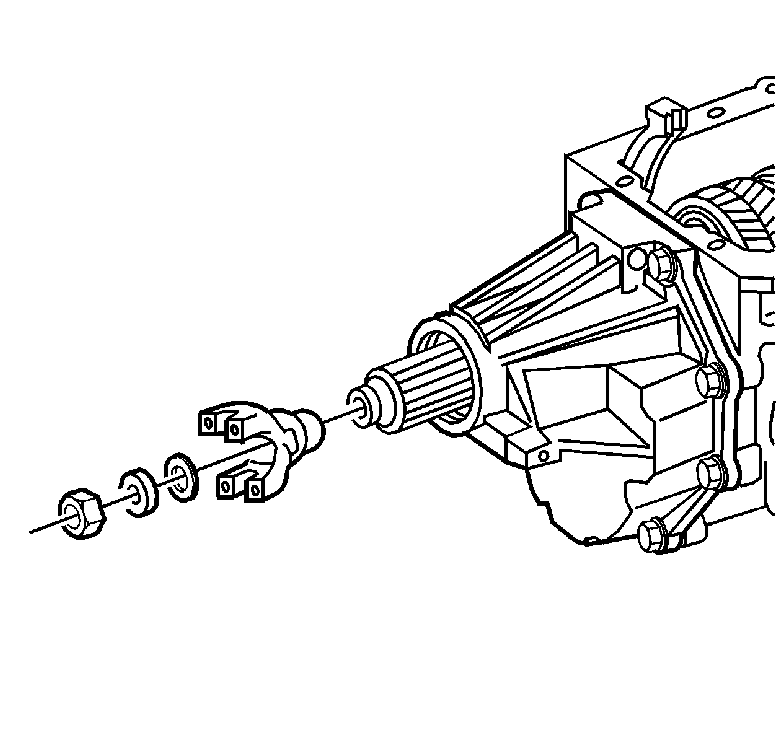
- For C model, remove
the following parts:
| 7.2. | The washer and discard |
| 7.3. | The rubber washer and discard |
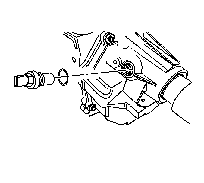
- For C model, remove
the vehicle speed sensor and the O-ring seal.
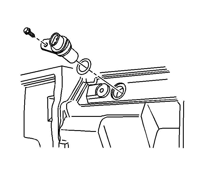
- For C 3500 HD,
remove the vehicle speed sensor bolt.
- Remove the vehicle speed sensor.
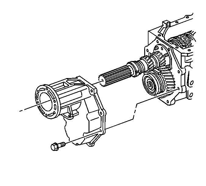
- For K model, remove
the transmission extension bolts.
- Remove the transmission extension.
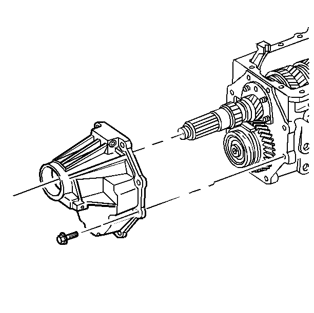
- For C 3500 HD
and C model, remove the transmission extension bolts. C model
shown.
- Remove the transmission extension.
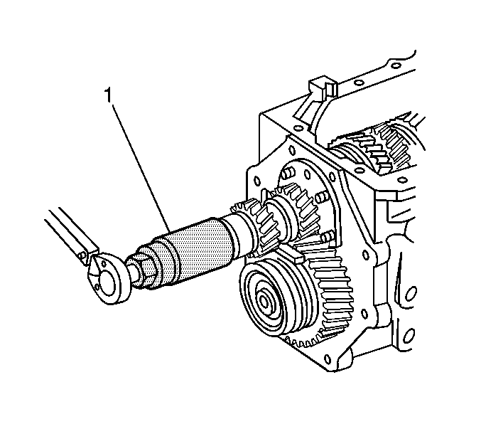
- For K model, using
the J 38805
(1),
remove the mainshaft nut and washer.
- Discard the washer.
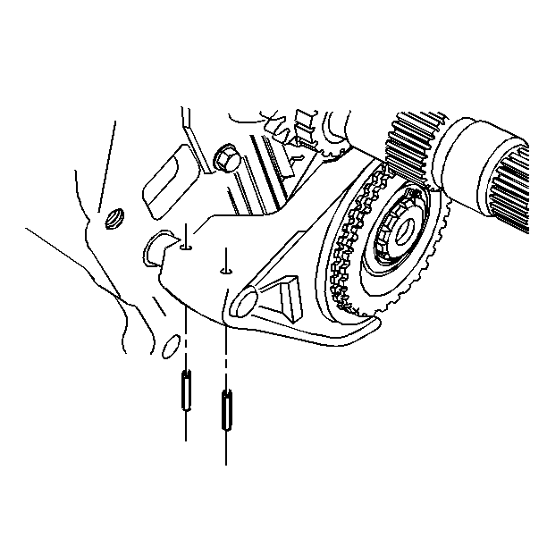
Important: Use the correct size punch when removing the shift fork roll pins. If
the punch is too large, it may flare the shaft rail and cause hard removal
of the shift fork.
- Remove the overdrive gear shift fork roll pins.
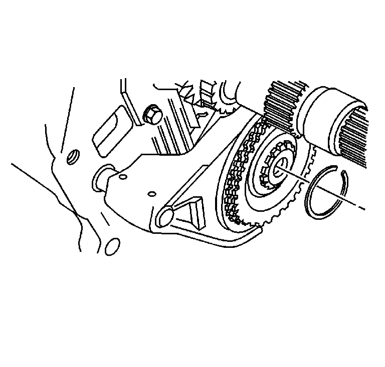
- Remove the overdrive gear
retainer ring.
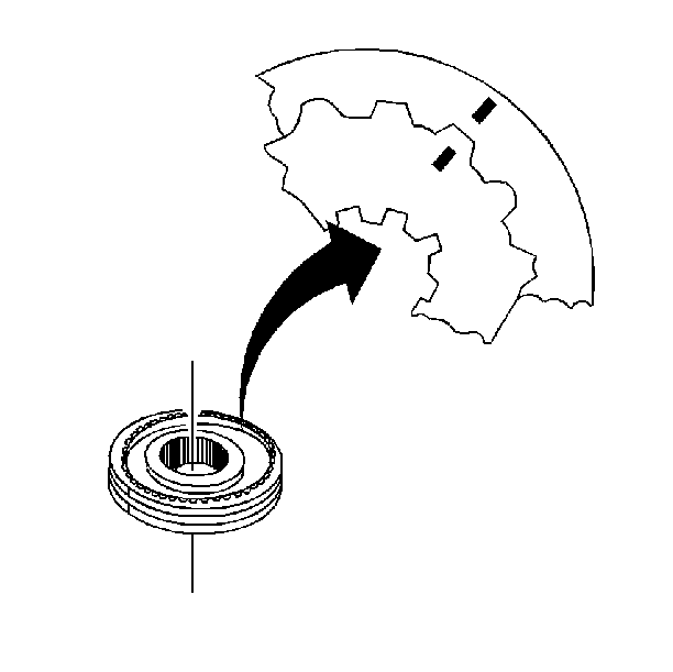
Important: For installation alignment, scribe an alignment mark on the synchronizer
hubs and synchronizer sleeves before removing. To prevent the synchronizer
springs and struts from being lost, do not separate the synchronizer
hubs from the synchronizer sleeves. Keep the synchronizer clutch gear
and the blocking rings with the synchronizer hubs. Organize the components
in order to install the components in their original location and
position.
- Scribe a mark on the overdrive synchronizer hub and synchronizer hub
sleeve.
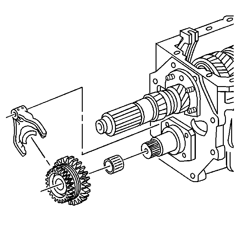
- Remove the overdrive gear
assembly, with the shift fork, from the countershaft.
- Remove the roller bearing.
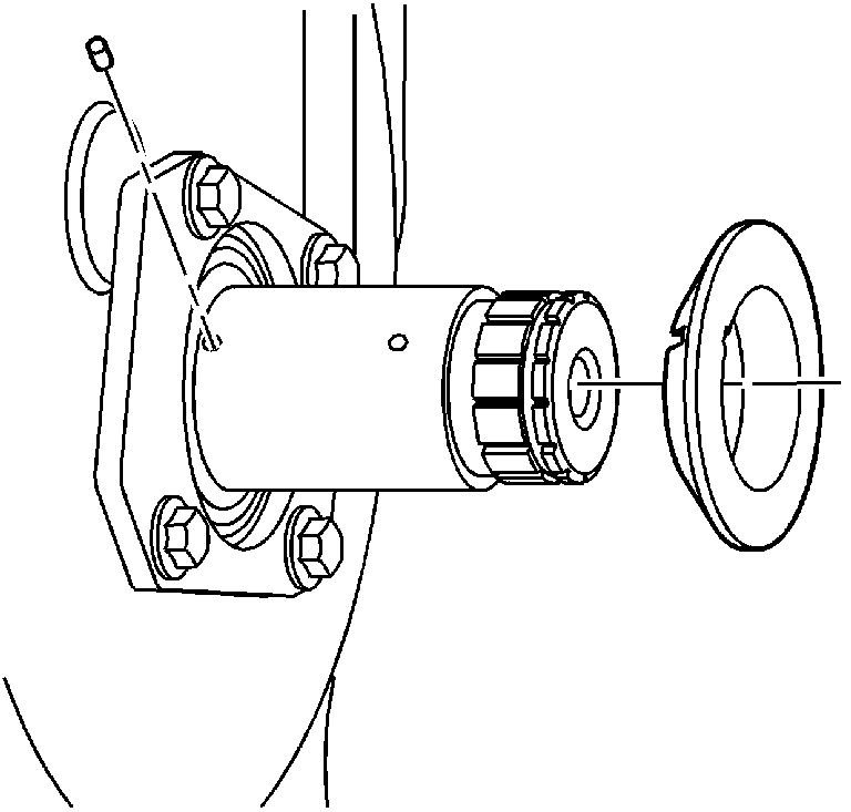
- Remove the thrust washer.
- Remove the thrust washer pin from the countershaft.
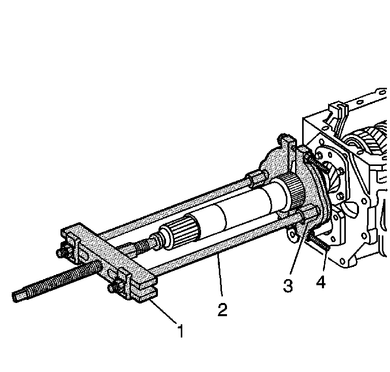
Important: Only remove the spacer and the vehicle speed sensor reluctor during
this procedure. The spacer and the speed sensor reluctor are press fit.
- For C 3500 HD, remove the spacer and the vehicle speed
sensor reluctor using J 44707
(1), J 45546
(2), J 45545
(3) and J 22912-B
(4) or equivalent.
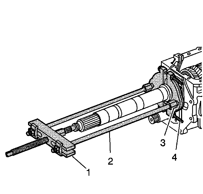
- For C 3500 HD,
remove the mainshaft overdrive gear using J 44707
(1), J 45546
(2), J 45545
(3) and J 22912-B
(4).
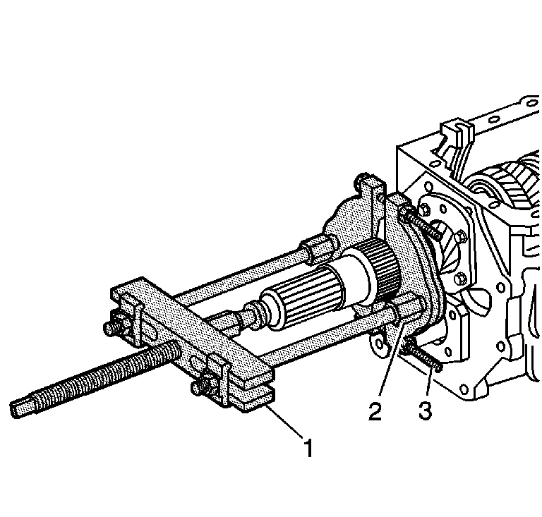
Important: Only remove the vehicle speed sensor during this procedure.
- For C model, remove the vehicle speed sensor reluctor using J 44707
(1), J 45545
(2) and J 22912-B
(3) or equivalent.
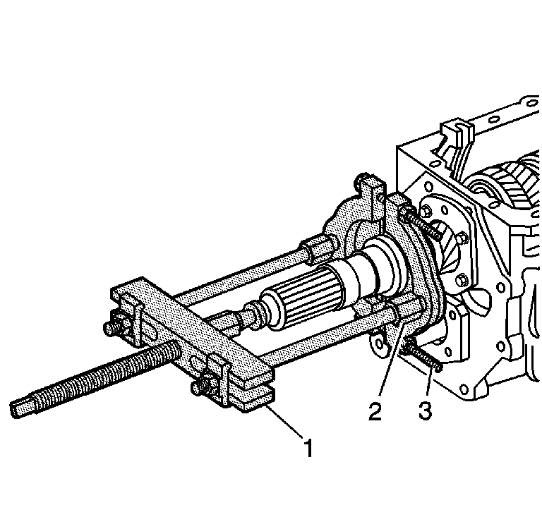
- For C model, remove
the mainshaft overdrive gear using J 44707
(1), J 45545
(2) and J 22912-B
(3), or equivalent.
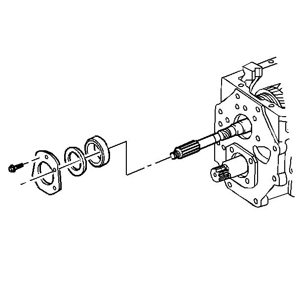
- Remove the mainshaft rear
bearing retainer bolts.
- Remove the mainshaft rear bearing retainer.
- Remove the shim or shims.
- Remove the mainshaft rear bearing cup.
- Move the synchronizer sleeves into the neutral position.
- Position the overdrive gear shift lever over to the side and hold
in position with a rubber band.
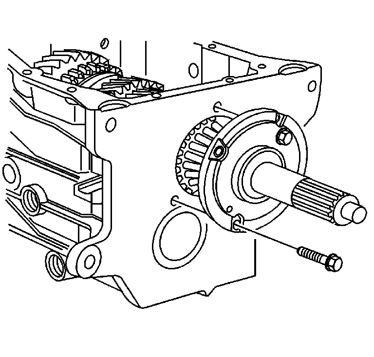
- For installation alignment,
mark the input shaft bearing retainer to the transmission case.
- Remove the input shaft bearing retainer bolts.
- Remove the input shaft retainer.
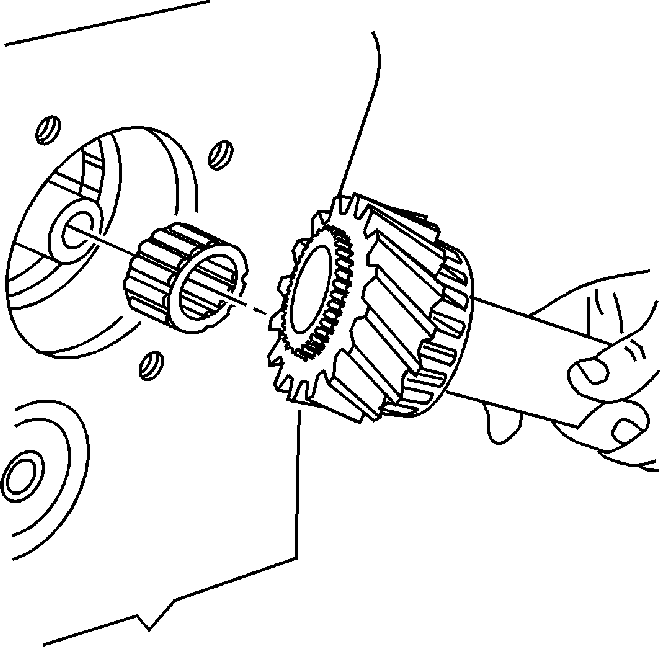
- Remove the input shaft.
- Remove the main drive gear bearing.
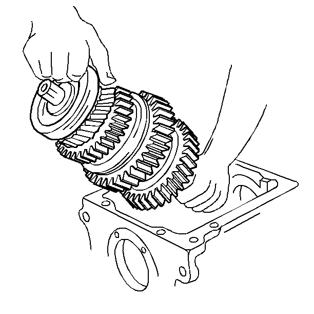
- Use the following procedure
in order to remove the mainshaft assembly from the case:
| 39.1. | Lift the mainshaft and move to the rear of the case. |
| 39.2. | Tip the front of the mainshaft up and remove the mainshaft from
the case. |
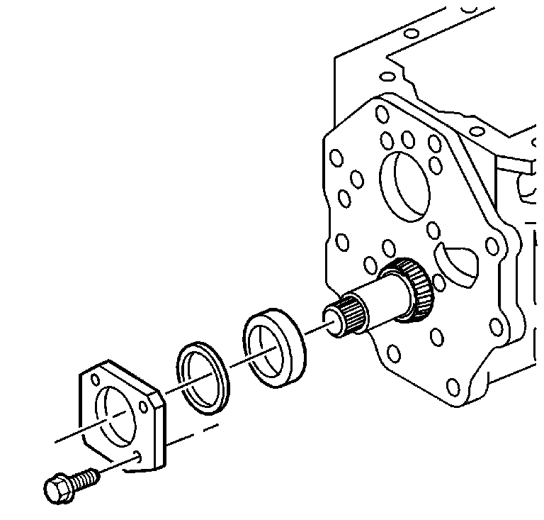
- Remove the countershaft
bearing retainer bolts.
- Remove the countershaft bearing retainer.
- Remove the shim or shims.
- Remove the countershaft rear bearing cup.
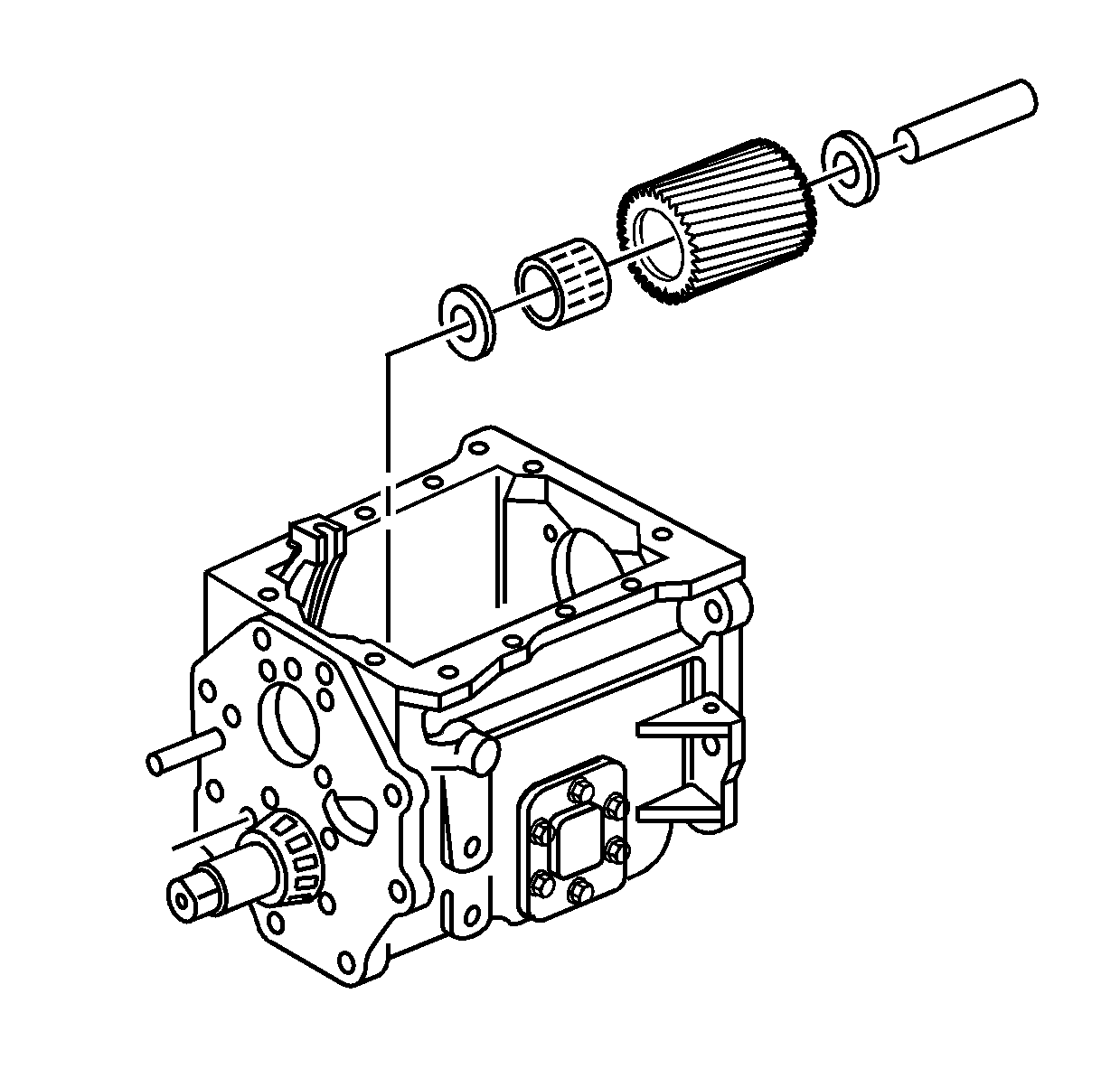
- Remove the reverse idler
gear and shaft:
| 44.1. | Using a suitable punch, drive the reverse idler gear shaft towards
the rear of the case. |
| 44.2. | Remove the reverse idler gear. |
| 44.3. | Remove the thrust washers. |
| 44.4. | Remove the bearing. |
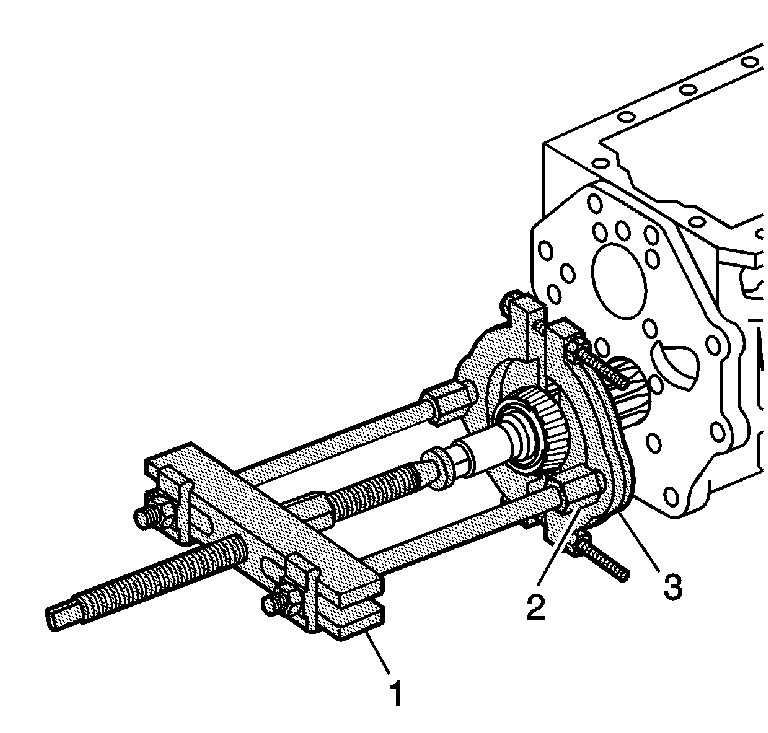
- Remove the countershaft
rear bearing using J 44707
(1), J 45545
(2) and J 22912-B
(3), or equivalent.
Removing the countershaft rear bearing will allow the countershaft to
be angled for removal.
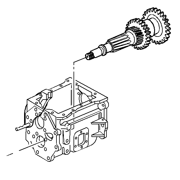
- Remove the countershaft
from the transmission case. Slide the countershaft rearward and lift the front
of the countershaft out of the case.
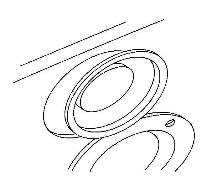
- Using a punch or chisel, remove the countershaft front bearing cap.
- Discard the removed bearing cap.
- Remove the countershaft front bearing cup.
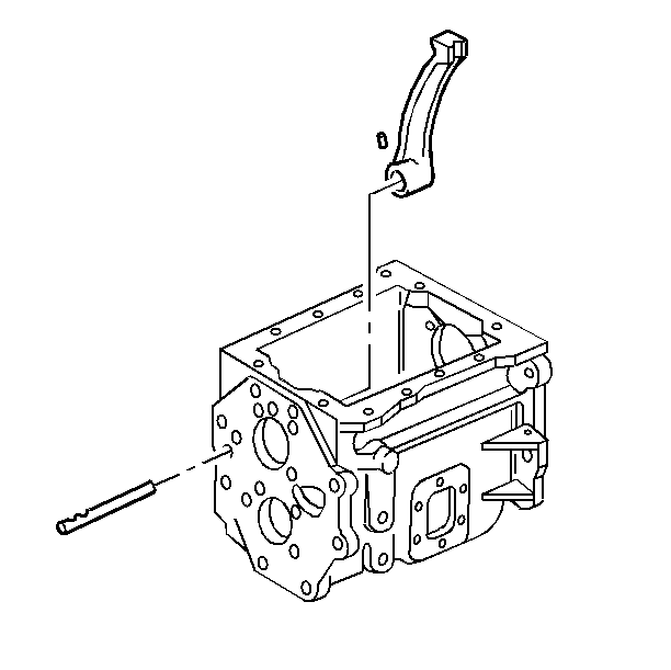
- Remove the roll pin from
the overdrive gear shift lever.
- Remove the shift lever shaft.
- Remove the overdrive gear shift lever.


