For 1990-2009 cars only
Removal Procedure
- Disable the SIR system. Refer to SIR Disabling and Enabling .
- Disconnect the negative battery cable. Refer to Battery Negative Cable Disconnection and Connection .
- Remove all of the related panels and the components.
- Visually inspect all of the damage forward of the rear module. Use 3-dimensional measuring in order to restore the damage to the factory specifications.
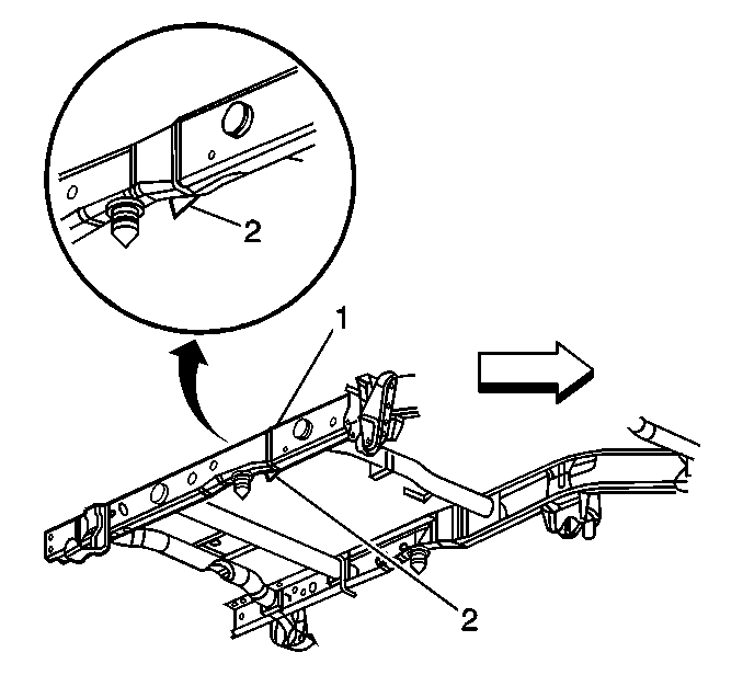
- Separate the center and the rear module at the factory stitch weld (1) with a die grinder or an appropriate tool.
- Pry the lower edge of cross tube bracket down (2) in order to allow the rear module to separate from the center module.
- Remove the damaged rear module.
Caution: Refer to Approved Equipment for Collision Repair Caution in the Preface section.
Caution: Refer to Collision Sectioning Caution in the Preface section.
Important: Perform all of the steps on both of the rails for complete module replacement.

Installation Procedure
Important: Monitor the specified dimensions by frequently performing 3-dimensional measuring throughout the procedures.
- Prepare all mating surfaces as necessary.
- Apply 3M Weld-Thru Coating P/N 05916 or equivalent to all mating surfaces.
- Install and position the replacement module using 3-dimensional measuring.
- Restore the bracket flange (2) for a flush fit to the new service part.
- Tack weld the rear module into position. Inspect the service part for the proper dimensions.
- Stitch weld the entire sectioning joint.
- Clean and prepare the welded surfaces.
- Apply approved anti-corrosion primer.
- Apply the sealers.
- Refinish the welded surfaces as necessary.
- Install all of the related panels and the components.
- Connect the negative battery cable. Refer to Battery Negative Cable Disconnection and Connection .
- Enable the SIR system. Refer to SIR Disabling and Enabling .

Important: Prior to refinishing, refer to GM 4901MD-99 Refinish Manual for recommended products. Do not combine paint systems. Refer to paint manufacturer's recommendations.
