Removal Procedure
- Drain the cooling system. Refer to Cooling System Draining and Filling in Engine Cooling.
- Disconnect the negative battery cable. Refer to Battery Negative Cable Disconnection and Connection in Engine Electrical.
- Remove the air cleaner outlet duct. Refer to Air Cleaner Outlet Duct Replacement .
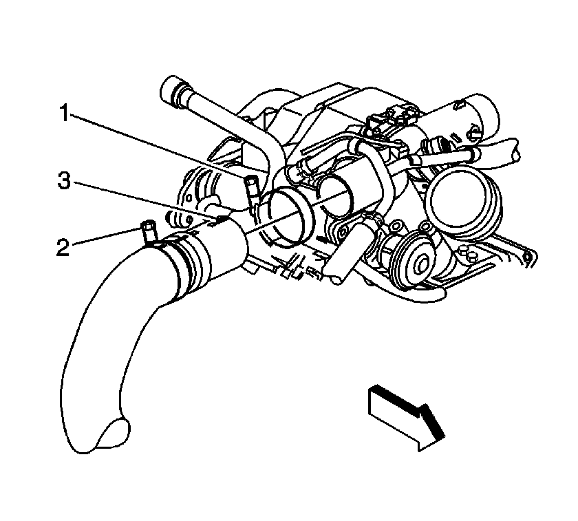
- Loosen the charged air cooler outlet duct clamp (1).
- Remove the charged air cooler outlet duct.
- Loosen the charged air cooler inlet duct to turbocharger clamp (1).
- Remove the charged air cooler inlet duct from the turbocharger.
- Remove the engine wiring harness. Refer to Engine Wiring Harness Assembly Replacement .
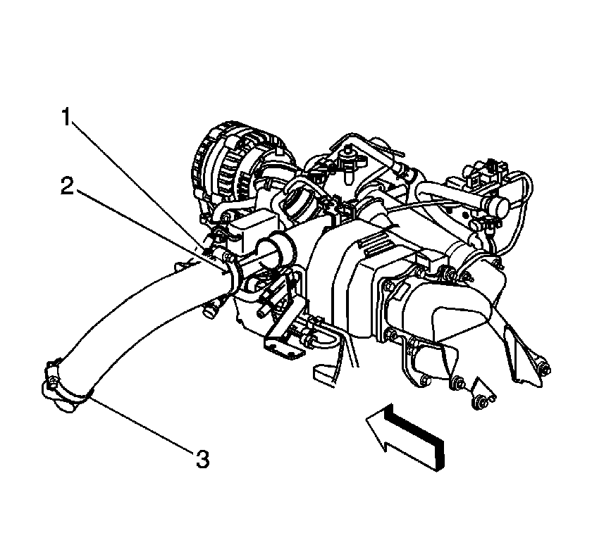
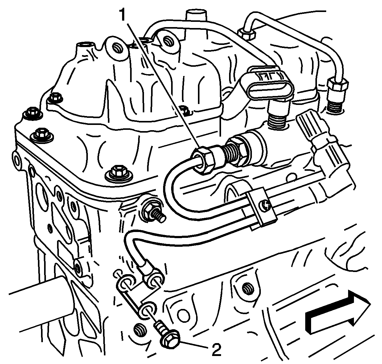
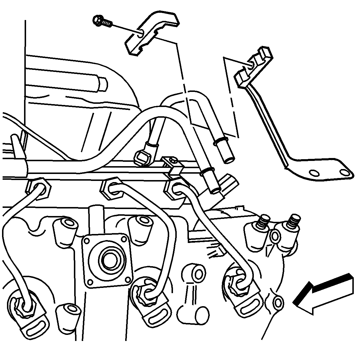
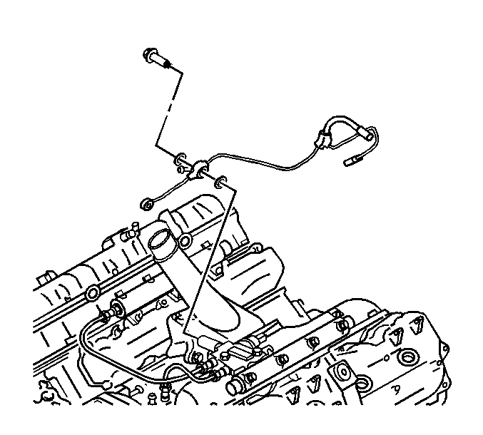
- Remove the fuel feed front pipe bracket nut.
- Remove the fuel feed front pipe (1).
- Reposition the fuel injection fuel feed front hose clamps.
- Remove the fuel injection fuel feed front hose.
- Remove the glow plug relay. Refer to Glow Plug Relay Replacement .
- Remove the fuel return rear pipe bolt (2) from the cylinder head.
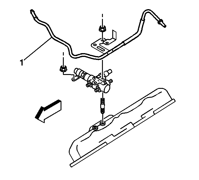
- Remove the fuel pipe clip bolt and clip.
- Remove the fuel return rear pipe bolt and pipe.
- Remove and discard the return pipe gaskets.
Important: Do not use a screwdriver or other tool to pry the hose loose. The hose can be torn or damage. Loosen the hose by twisting.
Important: Do not use a screwdriver or other tool to pry the hose loose. The hose can be torn or damage. Loosen the hose by twisting.
Installation Procedure
Important: Always install NEW copper gaskets onto the fuel injector fuel return pipe.
- Install NEW the return pipe gaskets.
- Install the fuel return rear pipe and bolt.
- Install the fuel pipe clip and bolt.
- Install the fuel return rear pipe bolt (2) to the cylinder head.
- Install the glow plug relay. Refer to Glow Plug Relay Replacement .
- Install the fuel injection fuel feed front hose.
- Reposition the fuel injection fuel feed front hose clamps.
- Install the fuel feed front pipe (1).
- Install the fuel feed front pipe bracket nut.
- Install the engine wiring harness. Refer to Engine Wiring Harness Assembly Replacement .
- Install the charged air cooler inlet duct to the turbocharger.
- Align the mark on the duct (2) with the mark on the turbocharger.
- Position the clamp (1) as shown for proper clearance.
- Install the charged air cooler outlet duct to the intake.
- Align the mark on the duct (3) with the mark on the turbocharger.
- Position the clamp (1) as shown for proper clearance.
- Install the air cleaner outlet duct. Refer to Air Cleaner Outlet Duct Replacement .
- Connect the negative battery cable. Refer to Battery Negative Cable Disconnection and Connection in Engine Electrical.
- Fill the cooling system. Refer to Cooling System Draining and Filling in Engine Cooling.
Notice: Use the correct fastener in the correct location. Replacement fasteners must be the correct part number for that application. Fasteners requiring replacement or fasteners requiring the use of thread locking compound or sealant are identified in the service procedure. Do not use paints, lubricants, or corrosion inhibitors on fasteners or fastener joint surfaces unless specified. These coatings affect fastener torque and joint clamping force and may damage the fastener. Use the correct tightening sequence and specifications when installing fasteners in order to avoid damage to parts and systems.
Tighten
Tighten the bolt to 27 N·m (19 lb ft).
Tighten
Tighten the bolt to 16 N·m (11 lb ft).
Tighten
Tighten the bolt to 15 N·m (11 lb ft).
Tighten
Tighten the nut to 8 N·m (70 lb in).
Tighten
Tighten the clamp to 6 N·m (53 lb in).
Tighten
Tighten the clamp to 6 N·m (53 lb in).
