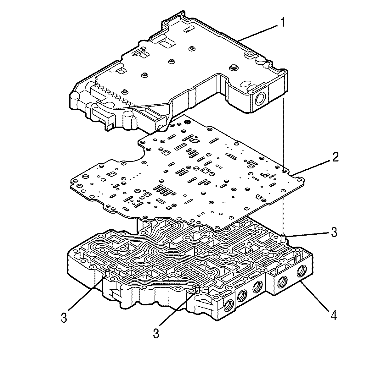
- Position the main valve body assembly (4) on the work table so that the worm-track side is up.
- Align the separator plate (2) with the main valve body locating pins (3).
- Install the separator plate (2).
- Align the shift valve body assembly (1) with the main valve body locating pins (3).
- Install the shift valve body assembly onto the separator plate.
- Position the control valve assembly on the work table so that the main valve body is facing up.
- Install 14 bolts (1) retaining the valve bodies together.
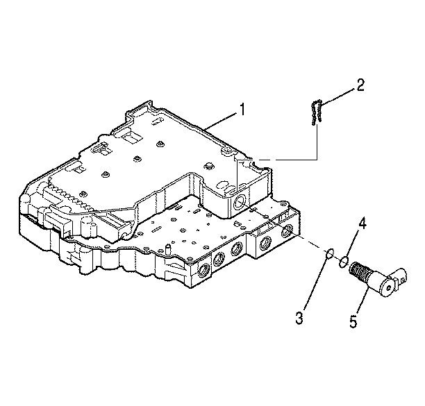
- Position the control valve assembly on the work table so that the shift valve body is up.
- Install the solenoid O-ring (4) onto the shift solenoid C (5).
- Install the solenoid O-ring (3) onto the shift solenoid C (5).
- Align the shift solenoid C (5) so that the electrical connector points away from the nearest locating pin and is parallel to the separator plate as shown.
- Position the control valve assembly on the work table so that the main valve body (16) is facing up.
- Install the solenoid O-ring (14) onto the pressure control solenoid A (15).
- Install the solenoid O-ring (8) onto the pressure control solenoid B (9).
- Install the spring (10), pressure control solenoid A valve (11), spring (12), and trim gain valve (13).
- Install the spring (5), pressure control solenoid B valve (6), and trim gain valve (7).
- Install the pressure control solenoid A (15) so that the electrical connection faces up. Do not seat the solenoid.
- Install the pressure control solenoid B (9) so the electrical connection faces up. Do not seat the solenoid.
- Align 2 accumulator plugs (3) so that their spring bores face up.
- Install 2 accumulator plugs (3) and 2 accumulator springs (2).
- Push the pressure control solenoids A and B into the bores until the solenoids seat.
- Align the pressure control valve retaining bracket (1) with the main valve body locating pin (4).
- Install the pressure control valve retaining bracket (1) so that the pressure control solenoids A and B, the accumulator plugs, and the accumulator springs are retained against the valve body.
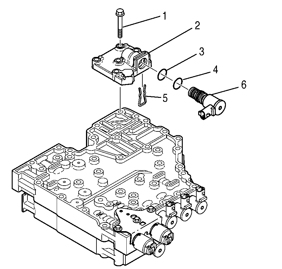
- Install 3 bolts (1) retaining the pressure control valve retaining bracket (2).
- Install the solenoid O-ring (3) onto the shift solenoid E (4).
- Install the solenoid O-ring (2) onto the shift solenoid E (4).
- Install the shift solenoid E (4) so that the electrical connection faces up. Seat the solenoid.
- Install the solenoid retainer (1).
- Install the solenoid O-ring (3) onto the shift solenoid D (4).
- Install the solenoid O-ring (2) onto the shift solenoid D (4).
- Install the shift solenoid D (4) so that the electrical connection faces up. Seat the solenoid.
- Install the solenoid retainer (1).
- Install the solenoid O-ring (6) onto the torque converter clutch pulse width modulated (TCC PWM) solenoid (7).
- Install the solenoid O-ring (5) onto the TCC PWM solenoid (7).
- Install the TCC PWM solenoid spring (2).
- Install the TCC PWM solenoid valve (3)
- Install the TCC PWM solenoid sleeve (4)
- Align the TCC PWM solenoid (7) so that the electrical connection faces up.
- Install the TCC PWM solenoid (7). Seat the solenoid.
- Install the solenoid retainer (1).
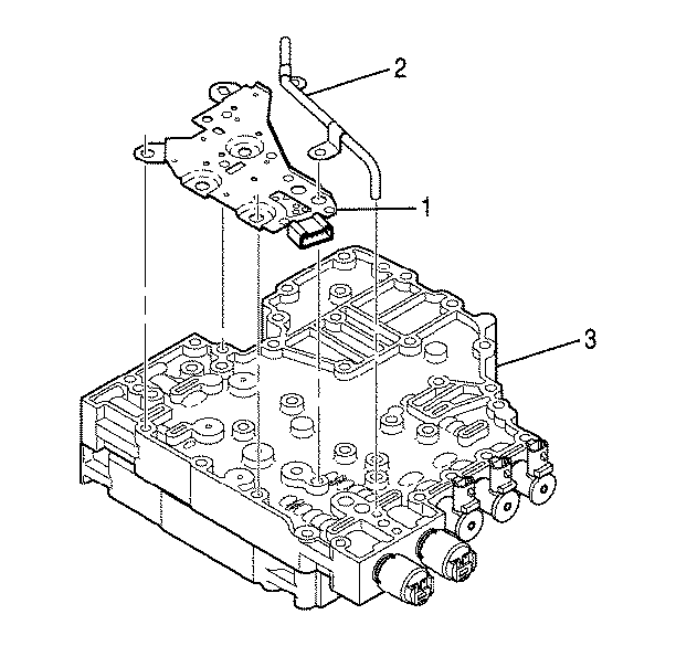
- Align the bolts holes and alignment tabs of the transmission fluid pressure (TFP) switch (1) with the TFP switch holes in the main valve body (1).
- Install the TFP switch (1) onto the main valve body (3).
- Install the reverse signal pipe (2) onto the main valve body.
- Install the O-rings (3) onto the modulated main pressure solenoid G (6).
- Install the modulated main pressure solenoid G (6)
- Install the modulated main pressure solenoid G retainer (5) into the bottom of the valve body.
- Install the modulated main pressure solenoid G body assembly (2).
- Install the 2 bolts retaining the modulated main pressure solenoid G valve body and the shift valve body to the main valve body.
- Install 6 bolts (1) and one bolt (2) retaining the reverse signal pipe and the TFP switch to the main valve body.
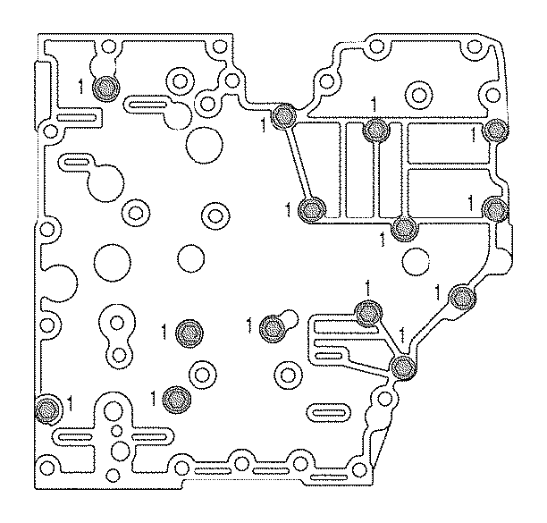
Tighten
Tighten the bolts to 12 N·m (9 lb
ft).
Important:
• The O-ring (4) is slightly larger than the O-ring (3). • P/N 29536833 is printed on the shift solenoid C (5).
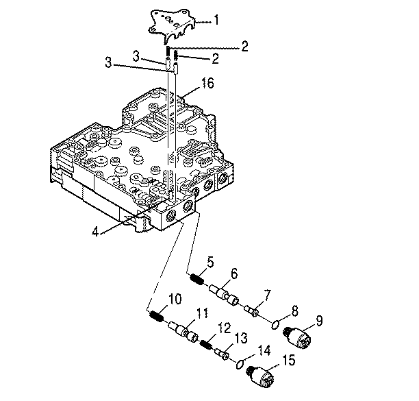
Important: P/N 29533074 is printed on the pressure control solenoid A.
Important: P/N 29533075 is printed on the pressure control solenoid B.
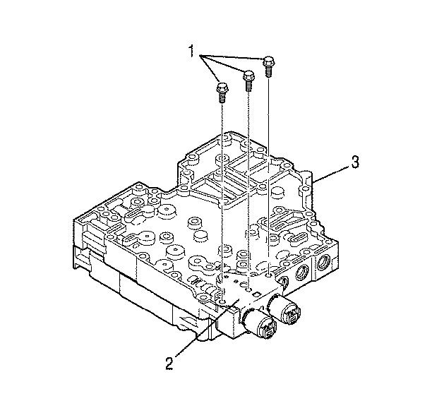
Tighten
Tighten bolts to 12 N·m (9 lb
ft).
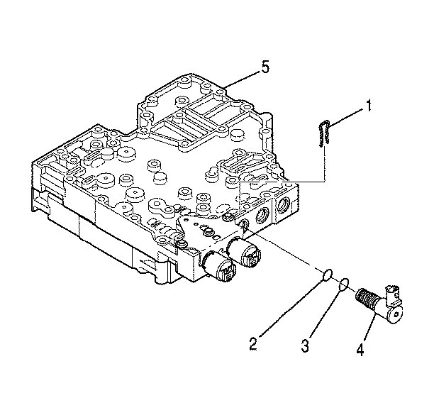
Important:
• The solenoid O-rings are brown. • The O-ring (3) is slightly larger than the O-ring (2). • P/N 29536833 is printed on the shift solenoid E.
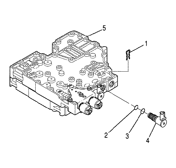
Important:
• The solenoid O-rings are brown. • The O-ring (3) is slightly larger than the O-ring (2). • P/N 29536833 is printed on the shift solenoid D.
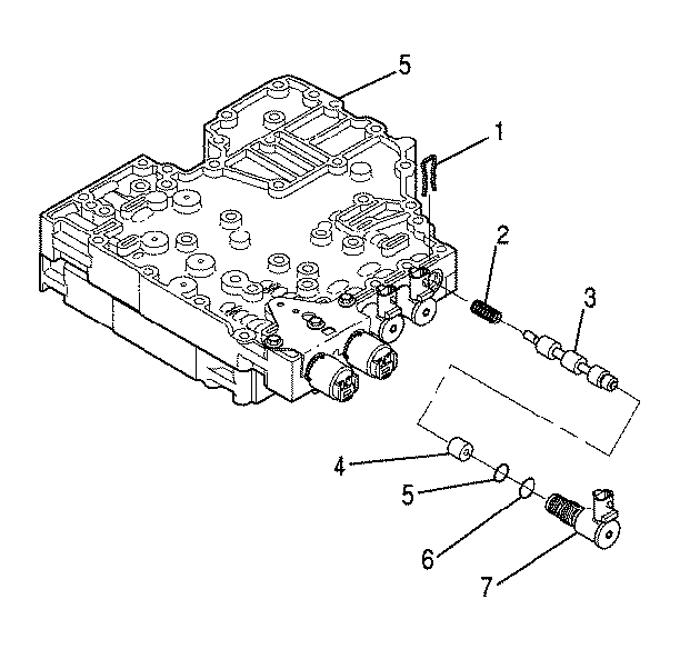
Important:
• The solenoid O-rings are brown. • The O-ring (6) is slightly larger than the O-ring (5).
Tighten
Tighten the bolts to 12 N·m (108 lb
in).
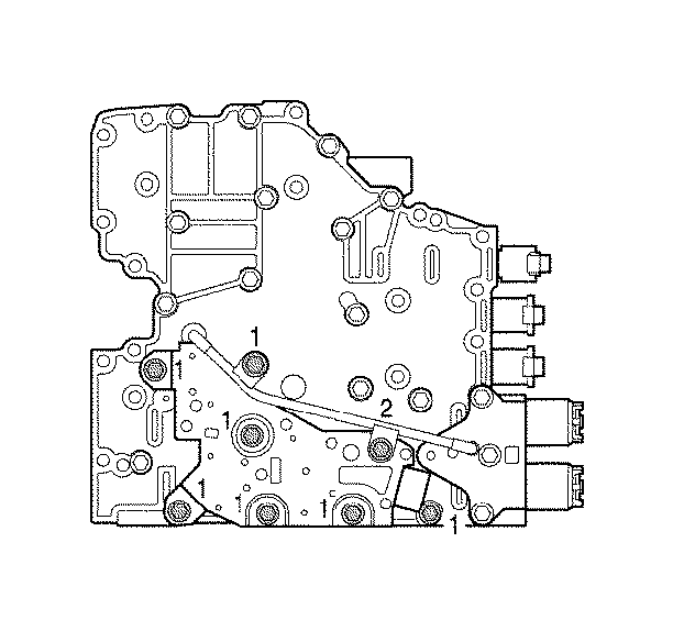
Important: Seven bolts retain the reverse signal pipe
and the TFP switch assembly.
• Bolt (2) is slightly longer than the other bolts (1). • The TFP switch is retained by 5 bolts (1) and by bolt (2). • The reverse signal pipe is retained by one bolt (1) and by bolt (2).
Tighten
Tighten bolts (1) and bolt (2) to 12 N·m
(9 lb ft).
