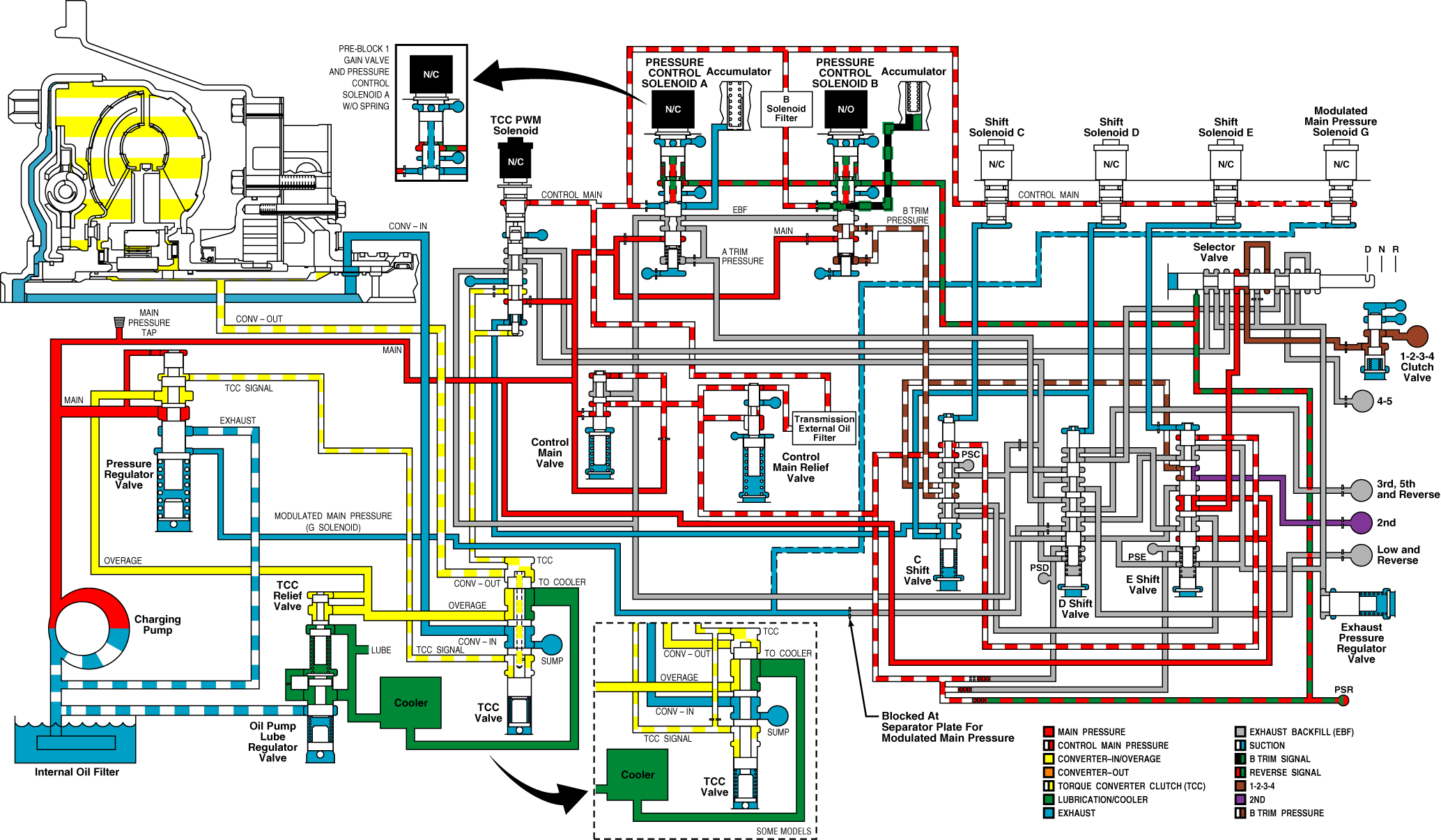
Second Range With TCC Applied (Tow-Haul)
Energizing the torque converter clutch pulse width modulated (TCC PWM) solenoid moves the valve downward against the stop, allowing main pressure to flow to the top of the converter flow valve. The converter flow valve is moved downward, exhausting converter-in pressure to sump, and eliminating the separating force between the TCC piston and the converter cover. At the same time, the converter flow valve opens the passage supplying TCC-apply pressure to the converter-out circuit. The pressure differential across the TCC piston applies the torque converter clutch.
Depending upon the calibration, TCC PWM solenoid could be energized in ranges 2-5. The calibrations can also apply the TCC for special applications such as power take-off (PTO) operation controlled directly by engine speed with transmission in Neutral (N) or TCC operation in first hold.
Second Range Without TCC Applied
Before shifting from first to second range, the transmission control module (TCM) makes certain the C, D, and E shift valves are in the correct position with the C and E shift valves up and the D shift valve down.
Pressure control solenoid A is energized, opening the A trim signal pressure to exhaust and allowing the A trim valve to move up, exhausting the low and Reverse clutch pressure. Pressure control solenoid B is energized, raising the B trim signal and B trim pressures. The B trim pressure is directed through the C and E shift valves to the 2nd Clutch. The TCM provides current to pressure control solenoid B, which controls the rate at which trim valve B supplies pressure to the 2nd clutch, and current to pressure control solenoid A, which controls the rate at which the low and Reverse clutch is exhausted, assuring a smooth transition to second range. Main pressure continues to feed through the E shift valve and manual valve, keeping the 1-2-3-4 clutch applied.
The combination of the 1-2-3-4 clutch and the 2nd clutch application produces second range operation.
After the shift to second range is complete, the shift solenoid D is de-energized allowing the D shift valve to move up. The low and Reverse clutch feed, which was exhausted through shift valve D and the A trim valve, now exhausts through exhaust backfill, keeping the low and Reverse clutch released. 3rd, 5th, and Reverse clutch has an exhaust path through shift valve D to the A trim valve, keeping the 3rd, 5th, and Reverse clutch released.
Pressure switches C, D and E turn off, providing feedback that the valves are in the upward position.
If electrical power is interrupted with the transmission in second range, pressure control solenoid A and B de-energize. The normally open pressure control solenoid B exhausts the B trim signal pressure, allowing the B trim valve to move up, exhausting the 2nd clutch. Normally closed pressure control solenoid A blocks the exhaust of A trim signal pressure, allowing the A trim signal and A trim pressures to rise. Trim valve A directs full trim pressure through the D shift valve to the 3rd, 5th, and Reverse clutch, applying the clutch. The 1-2-3-4 clutch continues to be applied with main pressure through the E shift valve and manual valve. The combination of the 1-2-3-4 clutch and the 3rd, 5th, and Reverse clutch applied produces third range converter operation for limp home capability.
If the torque converter clutch was applied during the power interrupt, TCC PWM solenoid is de-energized and the transmission returns to converter operation.
If electrical power is interrupted with the transmission in second range and subsequent third range operation, moving the manual valve to Neutral (N) will cut off main pressure to the 1-2-3-4 clutch and the clutch will be exhausted. The 3rd, 5th, and Reverse clutch remains applied. Because only one clutch is applied, the transmission goes to Neutral (N).
If electrical power is interrupted with the transmission in second range with subsequent third range operation, moving the manual valve to Reverse (R) will cut off main pressure to the 1-2-3-4 clutch, exhausting the 1-2-3-4 clutch. The manual valve directs main pressure through the TCC PWM valve and shift valve D to the low and Reverse clutch, applying the clutch. The 3rd, 5th, and Reverse clutch remains applied. The combination of the 3rd, 5th, and Reverse clutch and the low and Reverse clutch application produces Reverse (R) range operation for limp home capability.
Second Range

