For 1990-2009 cars only
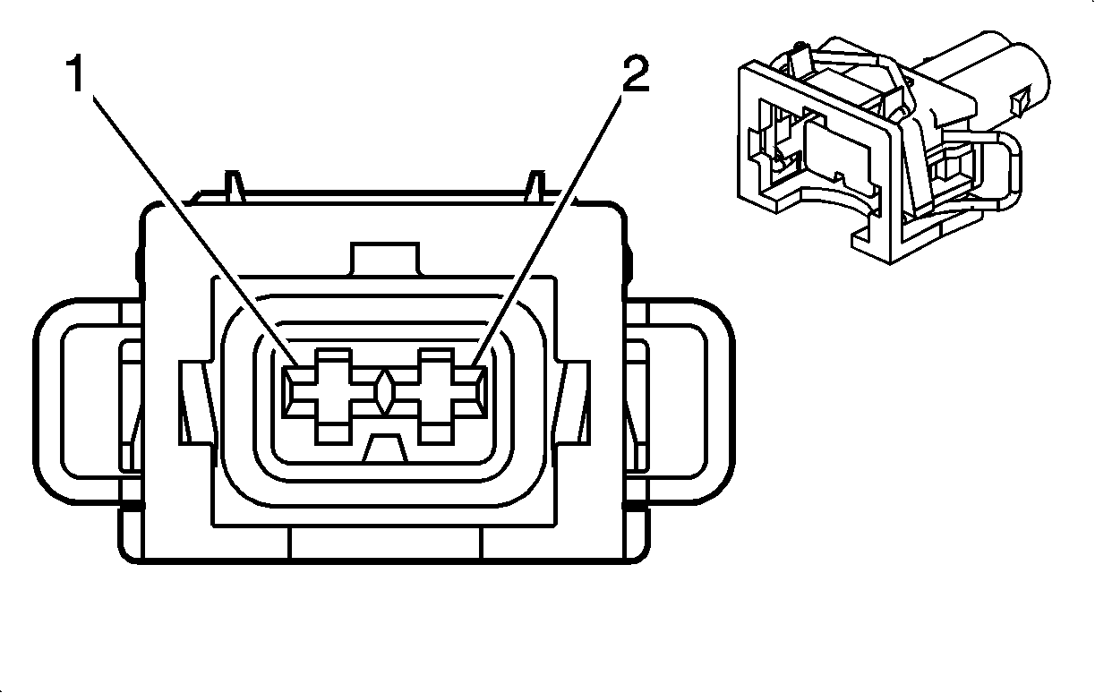
| Table 1: | Auxiliary Water Pump (HP2) |
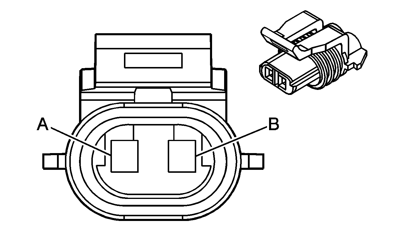
| Table 2: | Coolant Level Switch (8.1L) |
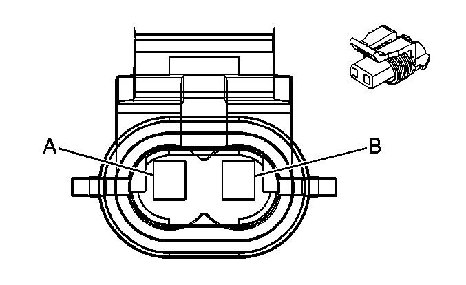
| Table 3: | Coolant Level Switch (Diesel) |
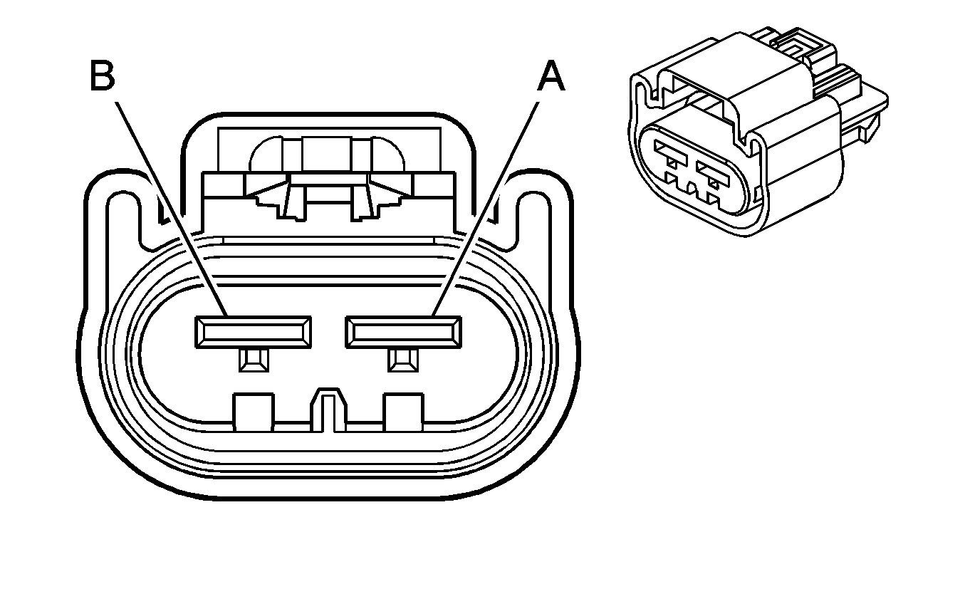
| Table 4: | Cooling Fan - Left (10 Series) |
| Table 5: | Cooling Fan - Right (10 Series) |
| Table 6: | Starter/Generator Control Module Coolant Pump (HP2) |

| |||||||
|---|---|---|---|---|---|---|---|
Connector Part Information |
| ||||||
Pin | Wire Color | Circuit No. | Function | ||||
1 | BK | 550 | Ground | ||||
2 | TN/WH | 5543 | Auxiliary Heater Pump Voltage | ||||

| |||||||
|---|---|---|---|---|---|---|---|
Connector Part Information |
| ||||||
Pin | Wire Color | Circuit No. | Function | ||||
A | L-GN | 1478 | Coolant Level Switch Signal | ||||
B | BK | 550 | Ground | ||||

| |||||||
|---|---|---|---|---|---|---|---|
Connector Part Information |
| ||||||
Pin | Wire Color | Circuit No. | Function | ||||
A | L-GN | 1478 | Coolant Level Switch Signal | ||||
B | BK | 550 | Ground | ||||

| |||||||
|---|---|---|---|---|---|---|---|
Connector Part Information |
| ||||||
Pin | Wire Color | Circuit No. | Function | ||||
A | YE | 5358 | Cooling Fan Motor Control | ||||
B | GY | 532 | Cooling Fan Motor Supply Voltage | ||||

| |||||||
|---|---|---|---|---|---|---|---|
Connector Part Information |
| ||||||
Pin | Wire Color | Circuit No. | Function | ||||
A | BK | 250 | Ground | ||||
B | L-BU | 409 | Cooling Fan Motor Supply Voltage | ||||

| |||||||
|---|---|---|---|---|---|---|---|
Connector Part Information |
| ||||||
Pin | Wire Color | Circuit No. | Function | ||||
1 | BK | 150 | Ground | ||||
2 | L-BU | 703 | Ignition 1 Voltage | ||||
