Tools Required
J 7872
Dial Indicator Set
- If a reciprocating component (crankshaft, connecting rod, piston, or bearings) has not been replaced, install the same grade head gasket that was removed.

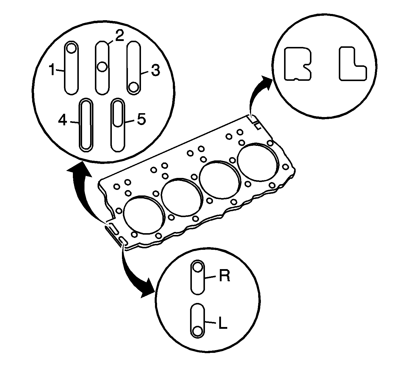
- The markings on the gasket are as follows:
| • | Block over-bored 0.010-0.030 in (0.254-0.762 mm) (4) |
| • | Block over-bored 0.010-0.030 in (0.254-0.762 mm) and deck milled 0.008 in (0.203 mm) (5) |
- The cylinder head gasket thickness is determined by the piston head projection from the cylinder block deck surface. There are cylinder head gaskets available in three different thicknesses. Follow the procedure below and refer to
Cylinder Head Gasket Selection Specifications
to determine what gasket to use for each bank of cylinders.
- Be sure the piston and cylinder deck are free of carbon, gasket material, or other objects that may give you an erroneous measurement.

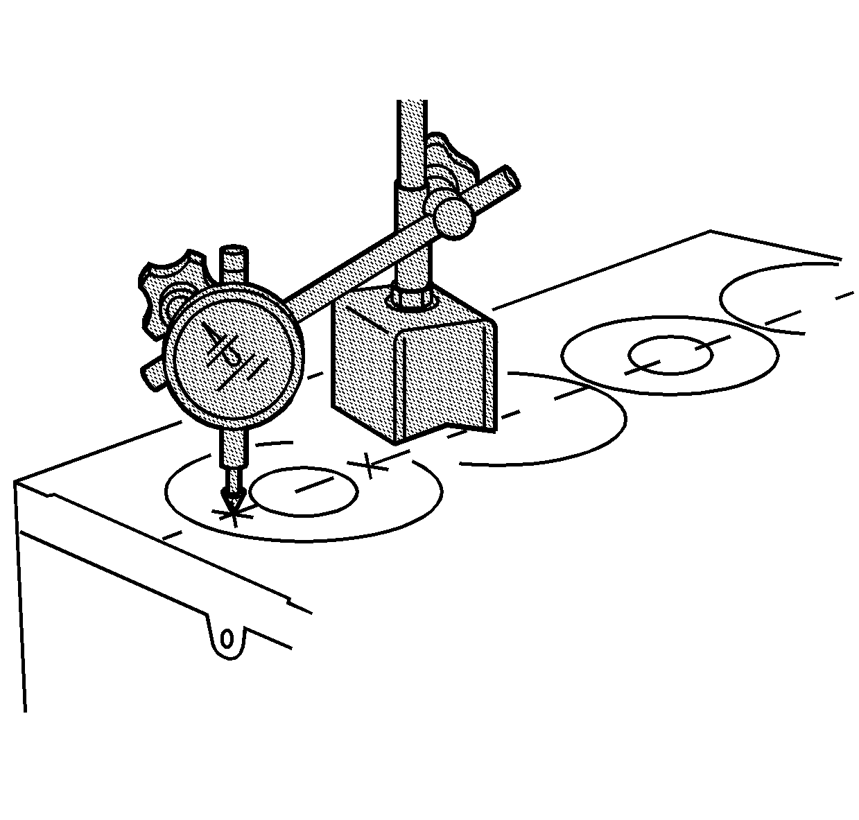
- Use
J 7872
to measure the piston projection across two different points on each
piston.
| 5.1. | Zero the dial indicator to the cylinder deck surface. |
| 5.2. | Place the dial indicator pointer on the piston top. Be sure the pointer is directly above the piston pin centerline to prevent inaccurate readings from piston rocking. |
| 5.3. | Rotate the engine to roll the piston through Top Dead Center while noting the maximum reading on the dial indicator. |
| 5.4. | Repeat procedure at the second measuring point on the piston. |
- Calculate the average value of piston projection for each cylinder.
- Obtain the maximum piston projection value for that bank of cylinders.
- Determine the gasket grade by the maximum piston projection value using the chart.
- If the difference between the highest measured piston head projection and the lowest measured piston projection, within one bank of cylinders, exceeds 0.1 mm (0.0039 in), then the following items need to be checked.
| • | Connecting rod to piston pin clearance |
| • | Piston to piston pin clearance |
If any of the above clearances are beyond specifications, then refer to the appropriate section for repair. If all of the above clearances are within the service limits but the piston projection variation is over 0.1 mm (0.0039 in), then
replace the connecting rod and piston assembly.


