Control Valve Solenoid Replacement Solenoid A, B
Removal Procedure
- Remove the oil pan and transmission internal oil filter. Refer to Oil Pan Replacement .
- Disconnect the internal wiring harness from the solenoid being changed.
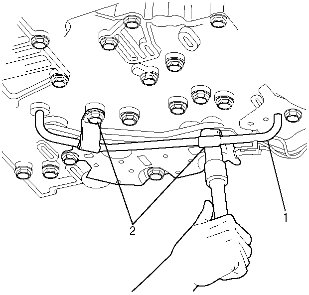
- Remove the 2 bolts (2) that fasten reverse signal pipe (1) to the control valve assembly. Remove the reverse signal pipe.
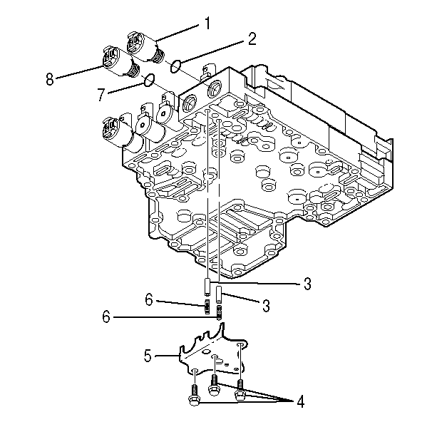
- To remove pressure control solenoid A (1) or pressure control solenoid B (8), remove three bolts (4) and the pressure control valve retaining bracket (5). Remove accumulators (3) and springs (6) if they do not fall out when bracket (5) is removed.
- Note the position of the solenoid connector and pull the solenoid (1) or (8) out of the bore in the control valve assembly. The O-ring on the solenoid provides the resistance felt during removal.

Important: The modulated main pressure solenoid G is removed for clarity.

Important:
• When the pressure control valve retaining bracket (5) is removed, there are 2 sets of accumulators (3) and springs (6) which may fall from the bores. Be sure to catch the accumulators and springs so as to prevent damage to these
parts. • The pressure control valve retaining bracket (5) must not be modified. Note that the angle between the 2 bracket surfaces is less than 90 degrees. Replace the bracket if the angle is 90 degrees or more.
Installation Procedure
- Obtain the new solenoid (1) or (8). Lubricate new O-ring (2) or (7) with clean transmission fluid. Install the O-ring and push the new solenoid into the control valve body bore with the wiring harness connector in the correct position.
- Reinstall the 2 accumulators (3) and springs (6) before installing the pressure control valve retaining bracket (5). The valve (3) goes in the bore first with the hollow end facing outward, followed by the spring (6) which goes inside the hollow portion of the valve.
- Install the pressure control valve retaining bracket (5), and install the 3 bolts (4).
- Install the reverse signal pipe. Install the 2 bolts (2) that fasten reverse signal pipe (1) to the control valve assembly.
- Reconnect the internal wiring harness to the solenoid.
- Install the oil pan and transmission internal oil filter. Refer to Oil Pan Replacement .

Notice: Use the correct fastener in the correct location. Replacement fasteners must be the correct part number for that application. Fasteners requiring replacement or fasteners requiring the use of thread locking compound or sealant are identified in the service procedure. Do not use paints, lubricants, or corrosion inhibitors on fasteners or fastener joint surfaces unless specified. These coatings affect fastener torque and joint clamping force and may damage the fastener. Use the correct tightening sequence and specifications when installing fasteners in order to avoid damage to parts and systems.
Tighten
Tighten the bolts to 12 N·m (108 lb in).

Tighten
Tighten the bolts to 12 N·m (108 lb in).
Control Valve Solenoid Replacement SolenoidC, D, E, F, G
Removal Procedure
- Remove the oil pan and the transmission internal oil filter. Refer to Oil Pan Replacement .
- Disconnect the internal wiring harness from the solenoid being changed.
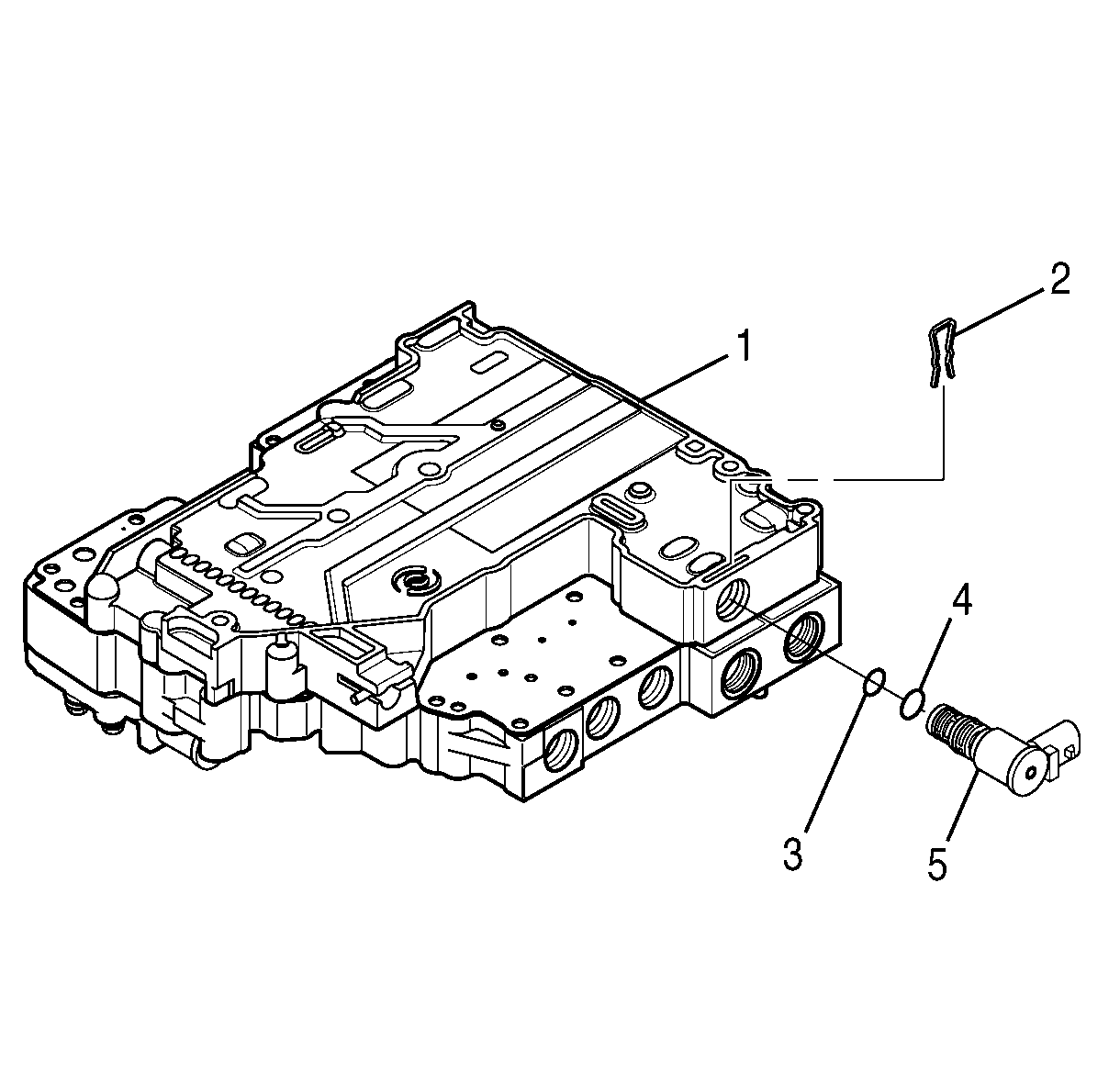
- Remove the solenoid retainer (2) for shift solenoid C (5). Note the position of the solenoid connector and pull the solenoid (5) out of the bore in the control valve assembly (1). The O-rings (3 and 4) provide the resistance felt during removal.
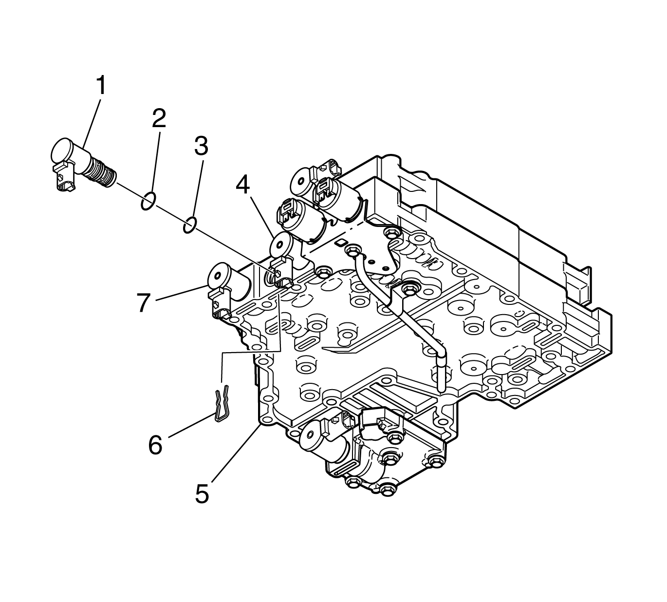
- Remove the solenoid retainers (6) for shift solenoid D (1), shift solenoid E (4), or the torque converter clutch pulse width modulated (TCC PWM) solenoid (7), whichever is being replaced.
- Note the position of the solenoid connector and pull the solenoid out of the bore in the control valve assembly. The O-rings (2 and 3) provide the resistance felt during removal.


Installation Procedure
- Obtain a new shift solenoid D (1), shift solenoid E (4), TCC PWM solenoid (7), or modulated main pressure solenoid G. Install O-rings (2 and 3) and lubricate with clean transmission fluid. Push the new solenoid into the control valve assembly (5) with the wiring harness connector in the correct position.
- Install the solenoid retainer (6). Connect the internal wiring harness to the solenoids replaced.
- For a new shift solenoid C (5), install O-rings (3) and (4) and lubricate with clean transmission fluid. Push the new shift solenoid C (5) into the control valve assembly with the wiring harness connector in the correct position. Install the solenoid retainer (2).
- Install the oil pan and transmission internal oil filter. Refer to Oil Pan Replacement .


