Disassembly Procedure
Tools Required
Notice: Refer to Transmission Control Valve Body Overhaul Notice in the Preface section.
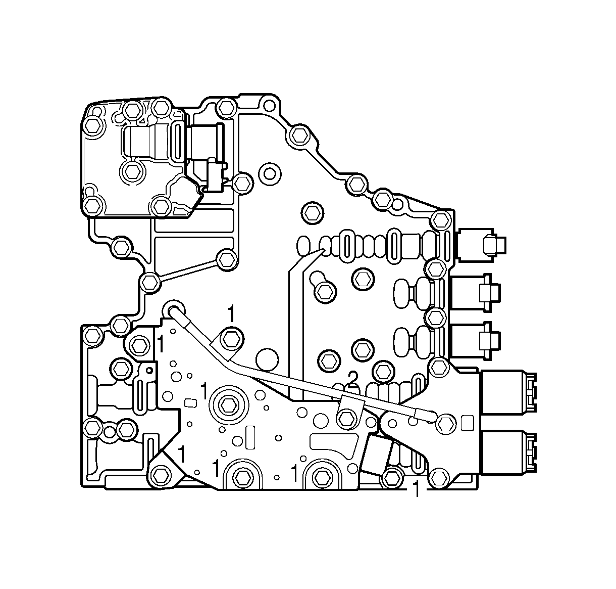
- Position the control valve module on the work table so that the main valve body module is facing up.
- Remove six bolts (1) and one bolt (2) retaining the reverse signal pipe and transmission fluid pressure (TFP) switch to the main valve body.
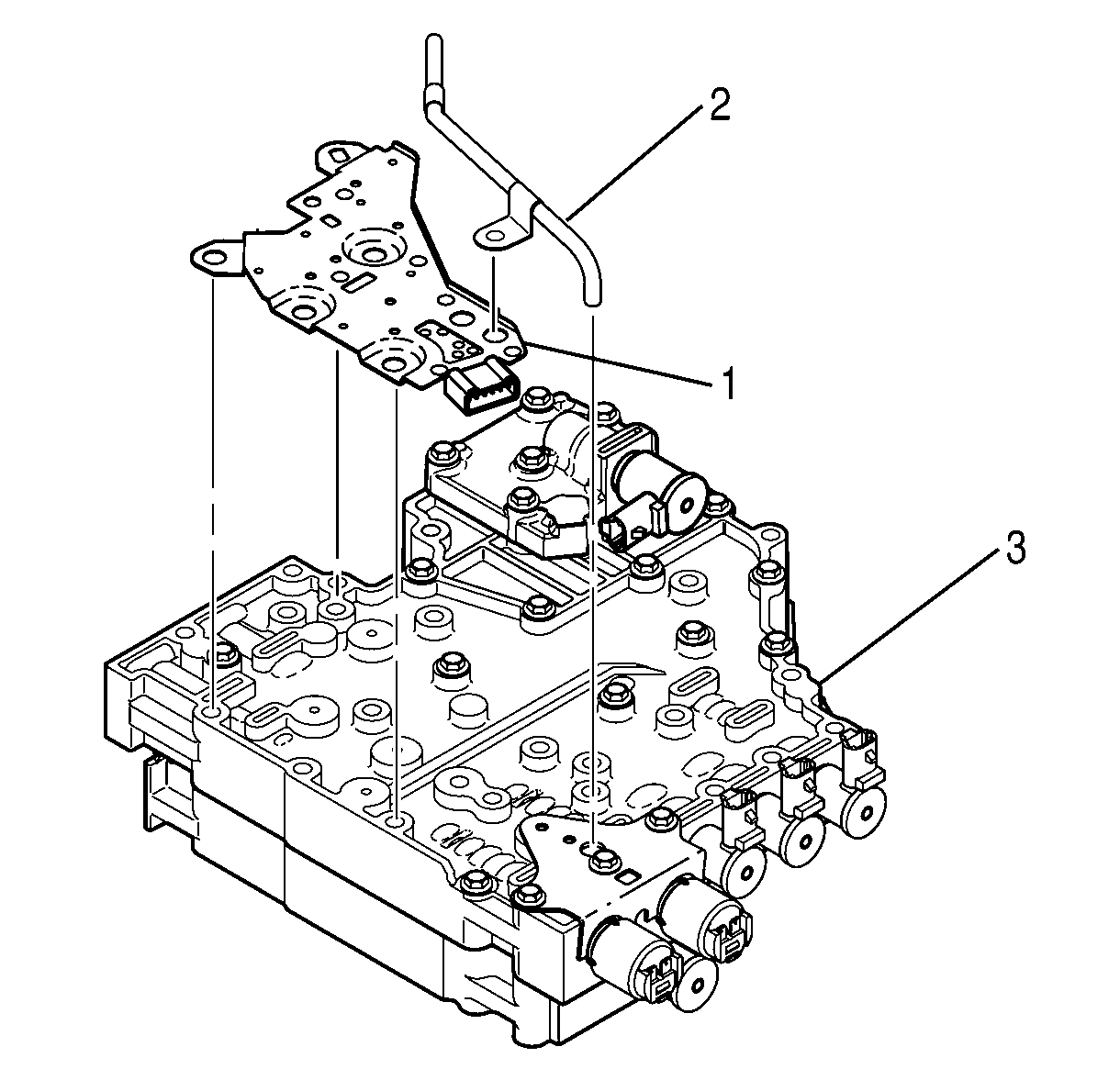
- Remove reverse signal pipe (2) from main valve body (3).
- Remove the TFP switch (1) from main valve body (3).
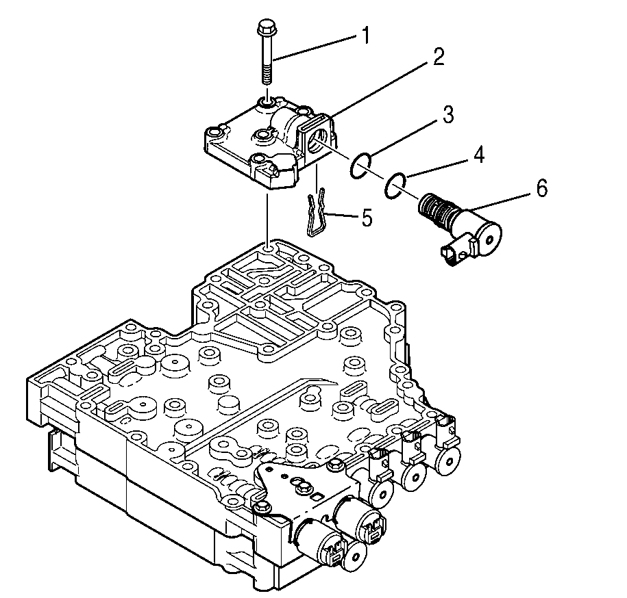
- Remove the 2 bolts (1) retaining the modulated main pressure solenoid G valve body (2).
- Remove the modulated main pressure solenoid G valve body assembly (2).
- Remove the modulated main pressure solenoid G retainer (5) from the bottom of the valve body (2).
- Remove the modulated main pressure solenoid G (6).
- Remove the 2 O-rings (3 and 4) from the modulated main pressure solenoid G (6).
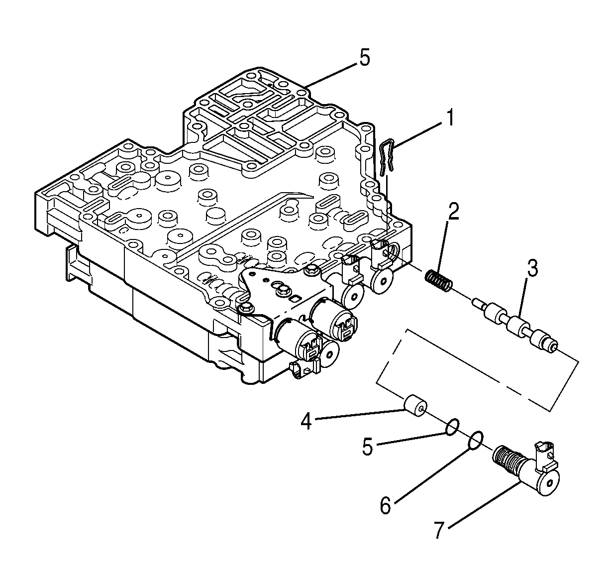
- Remove the torque converter clutch pulse width modulated (TCC PWM) solenoid retainer (1).
- Remove the TCC PWM solenoid (7), sleeve (4), valve (3), and spring (2).
- Remove O-rings (5) and (6) from the TCC PWM solenoid (7).
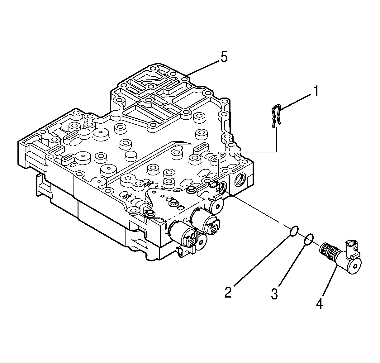
- Remove shift solenoid D retainer (1).
- Remove shift solenoid D (4).
- Remove the O-rings (2 and 3) from shift solenoid D (4).
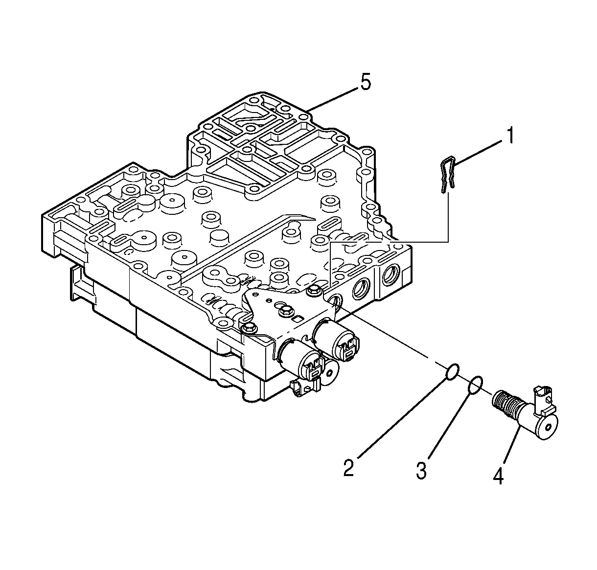
- Remove shift solenoid retainer E (1).
- Remove shift solenoid E (4).
- Remove the O-rings (2) and (3) from shift solenoid E (4).
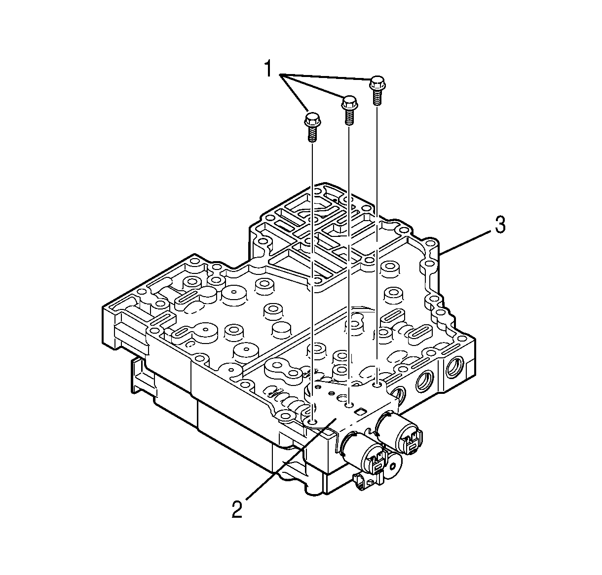
- Remove the 3 bolts (1) that retain the pressure control solenoid retaining bracket (2) to main valve body (3).
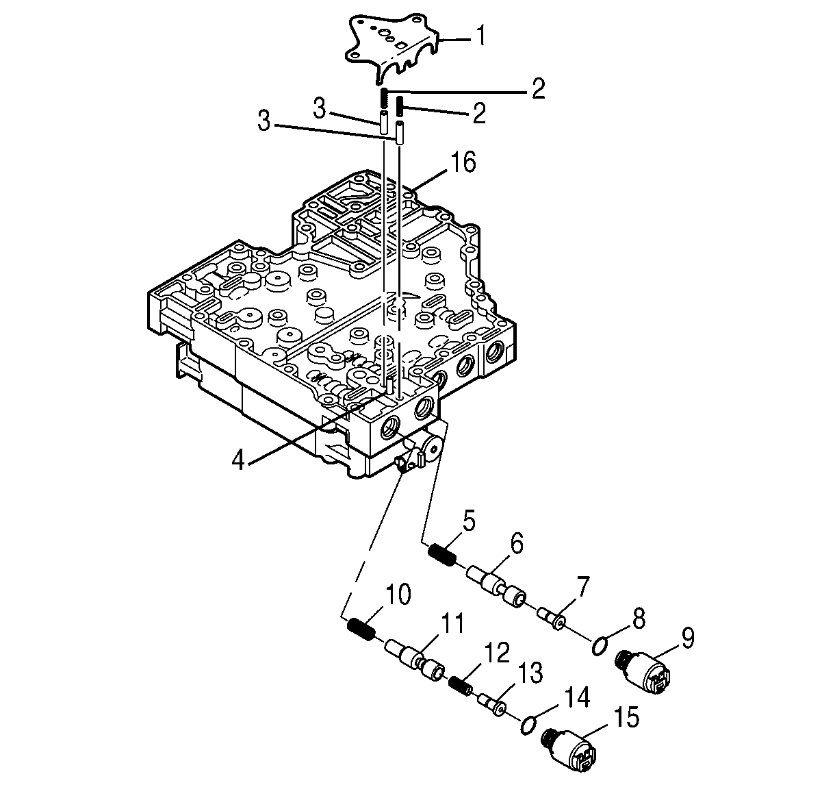
- Remove the pressure control solenoid retaining bracket (1), 2 accumulator springs (2), and 2 accumulator plugs (3).
- Remove pressure control solenoid A (15), valve (13), spring (12), valve (11), and spring (10).
- Remove pressure control solenoid B (9), valve (7), valve (6), and spring (5).
- Remove O-ring (14) from pressure control solenoid A (15).
- Remove O-ring (8) from pressure control solenoid B (9).
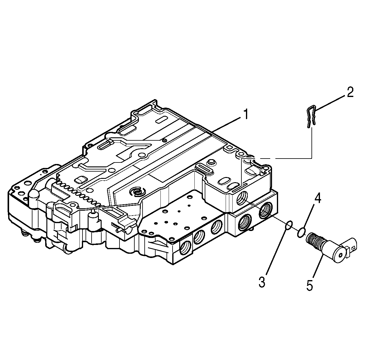
- Position the control valve module on the work table so that shift valve body (1) is facing up.
- Remove shift solenoid C retainer (2).
- Remove shift solenoid C (5).
- Remove O-rings (3 and 4) from shift solenoid C (5).
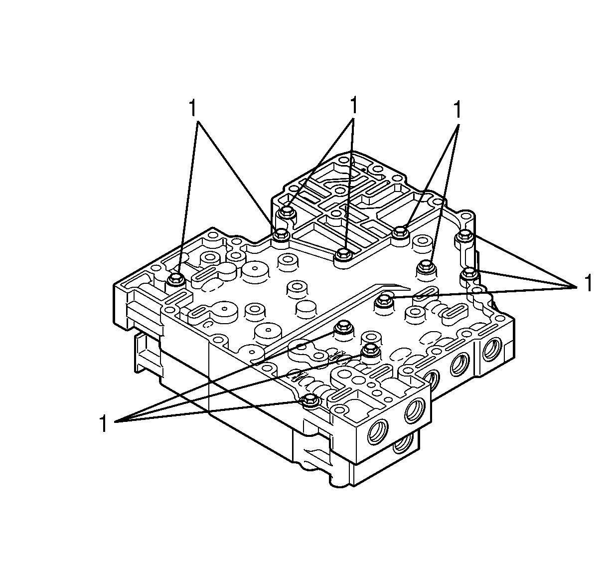
- Remove eleven bolts (1) retaining the shift valve body and the main valve body together.
- Position the control valve module on the work table so that the main valve body is facing up. Reinstall four bolts (1) so that the bolts are partially threaded into the shift valve body and protrude from the main valve body.
- Position the control valve module on edge so that the top and bottom are vertical.
- Gently tap the bolts until the module separates.
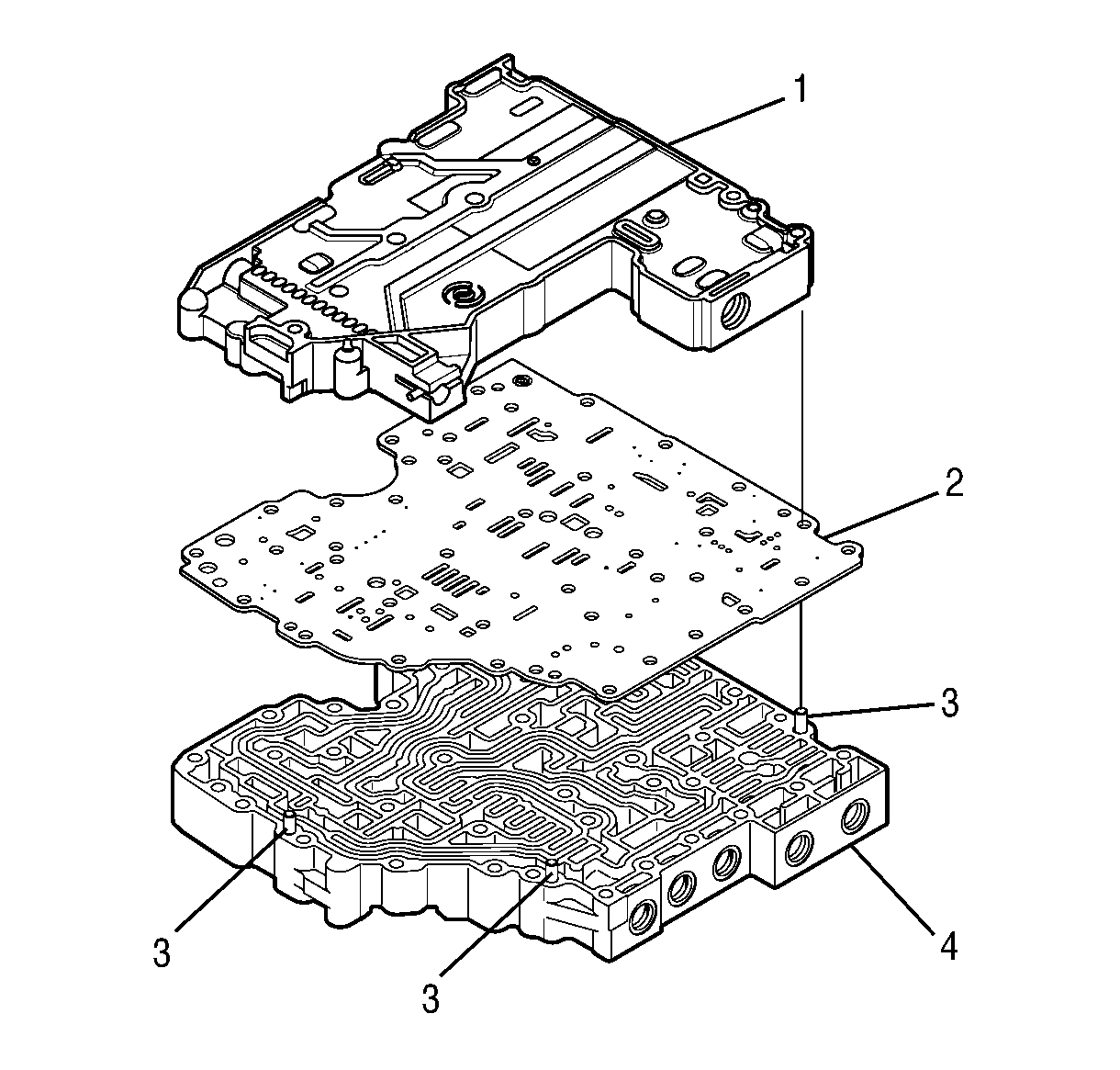
- Position the control valve assembly on the work table so that shift valve body (1) is facing up.
- Separate shift valve body assembly (1), separator plate (2), and main valve body assembly (4).
Disassembly of Shift Valve Body
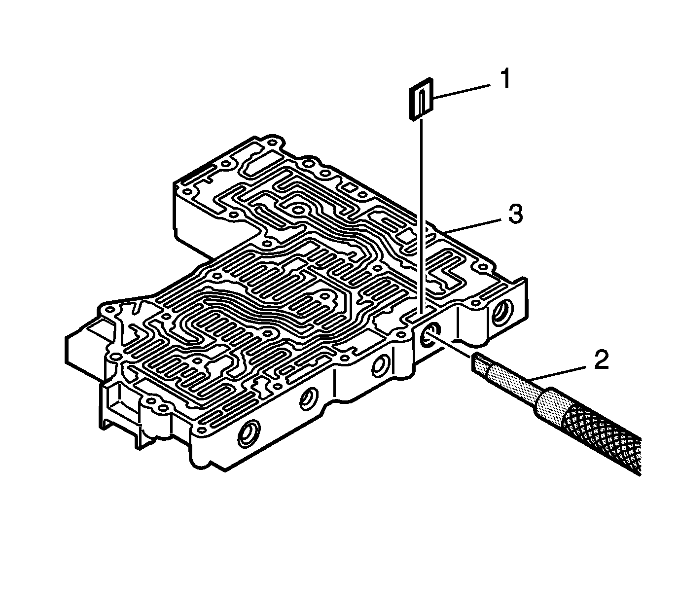
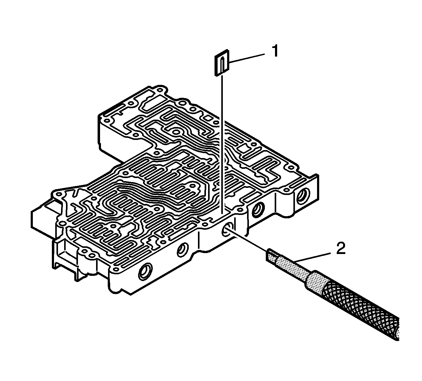
- Using
J 43773
(2) , compress the C shift valve spring until retaining
clip (1) is loose. Remove retaining clip (1).
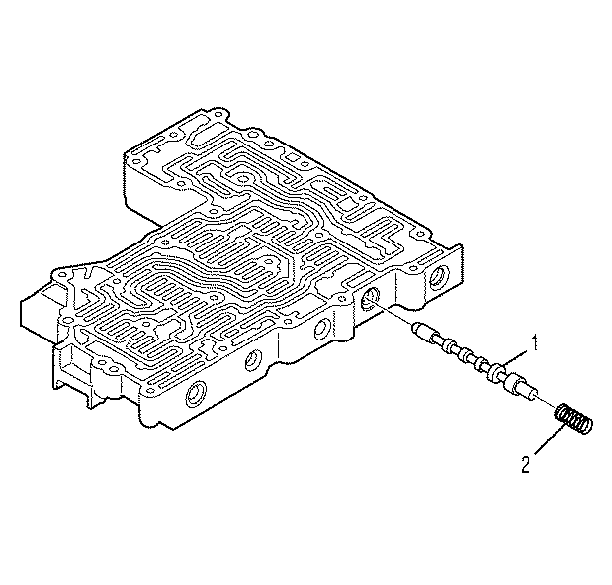
- Remove spring (2) and C shift valve (1).
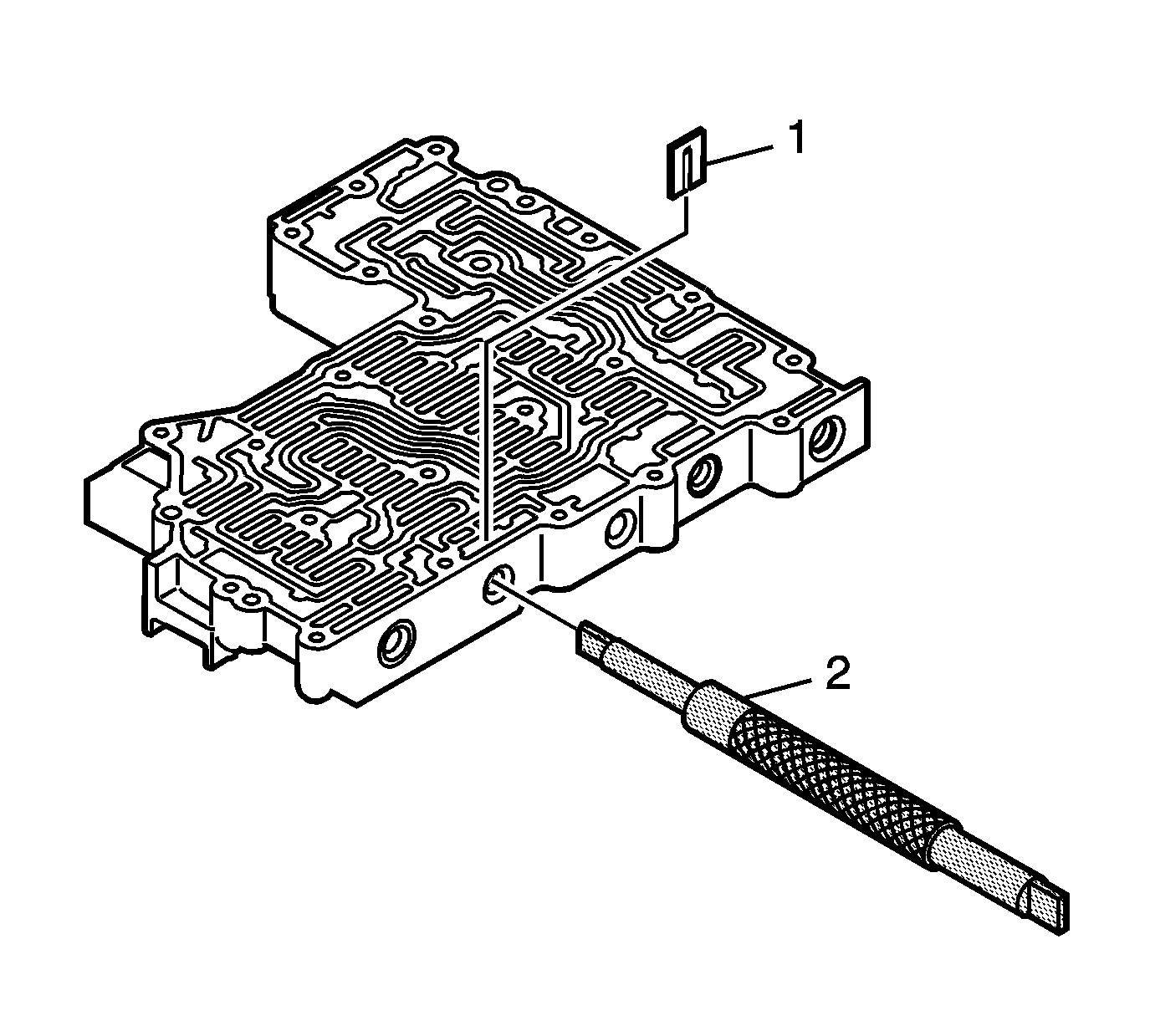
- Using
J 43773
(2), compress the E shift valve spring until retaining clip (1) is loose.
Remove retaining clip (1).
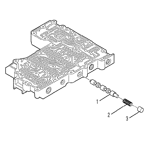
- Remove plug (3), spring (2), and E shift valve (1).
- Using
J 43773
(2), compress the D shift valve spring until retaining clip (1) is loose.
Remove retaining clip (1).
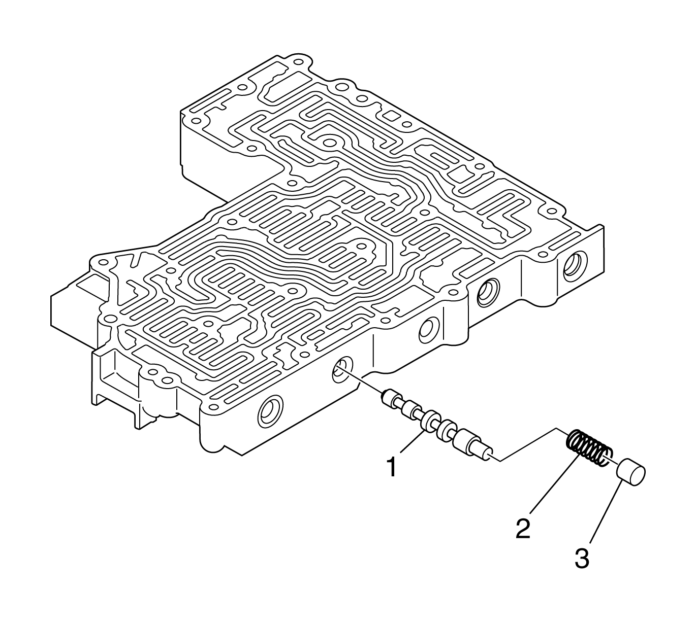
- Remove plug (3), spring (2), and D shift valve (1).
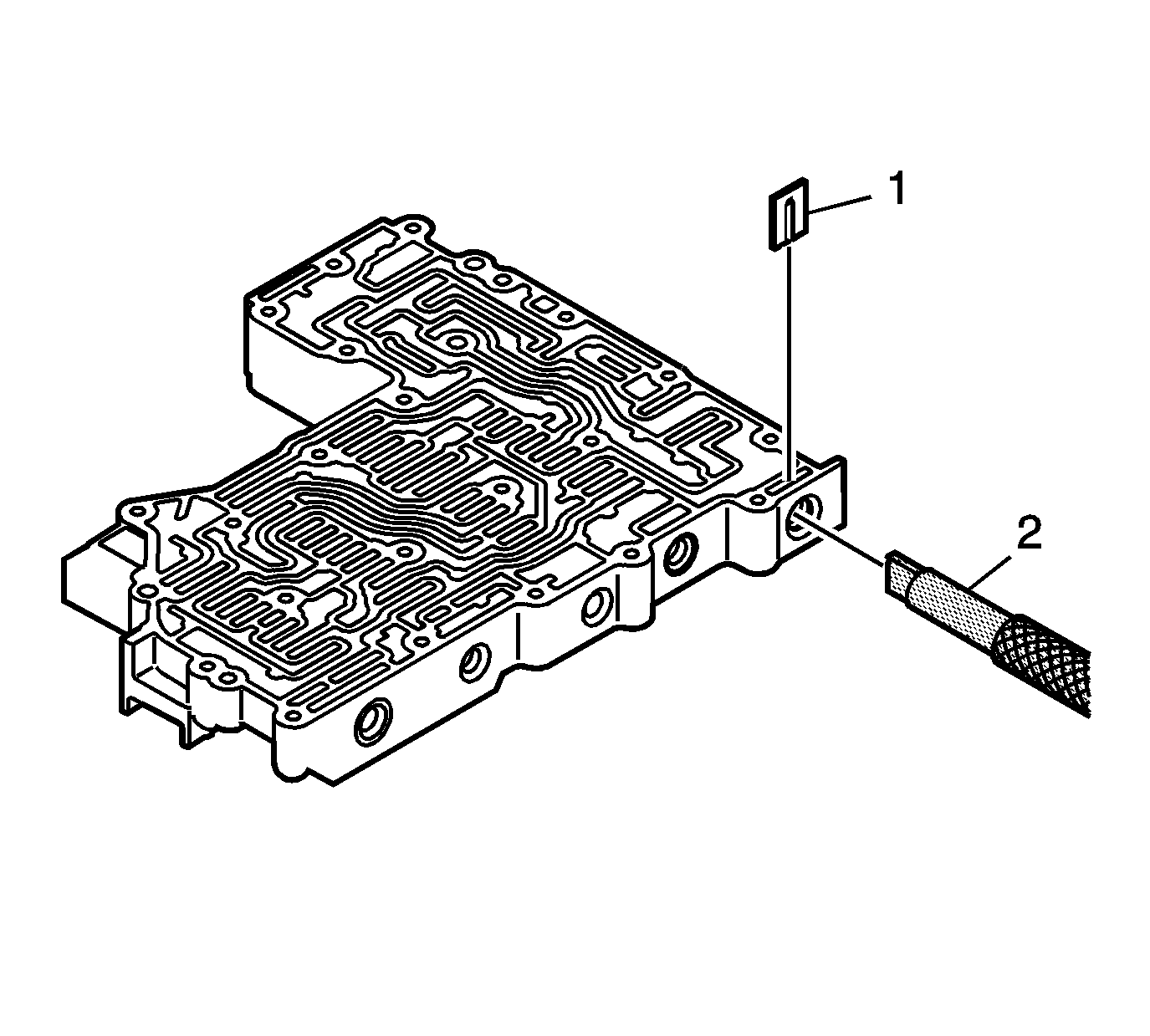
- Using
J 43773
(2), compress the control main valve spring until retaining
clip (1) is loose. Remove retaining clip (1).
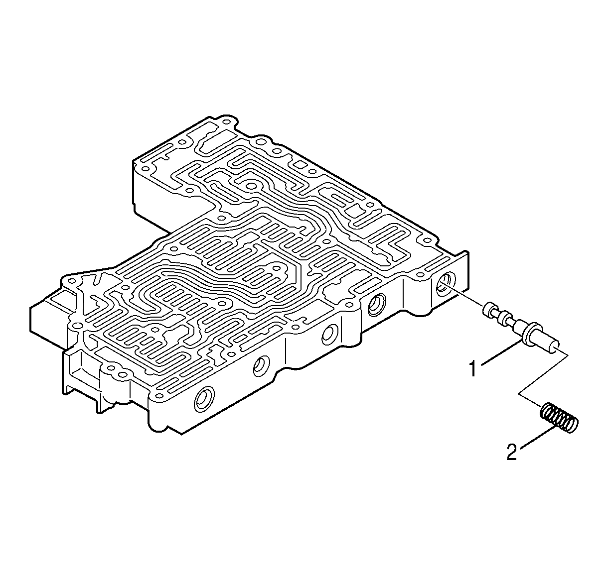
- Remove spring (2) and control main valve (1).
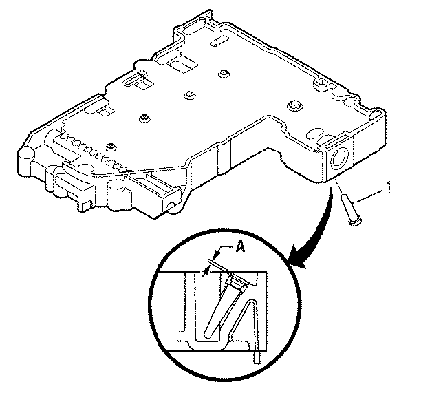
- Remove solenoid screen (1).
Disassembly of Main Valve Body
Tools Required
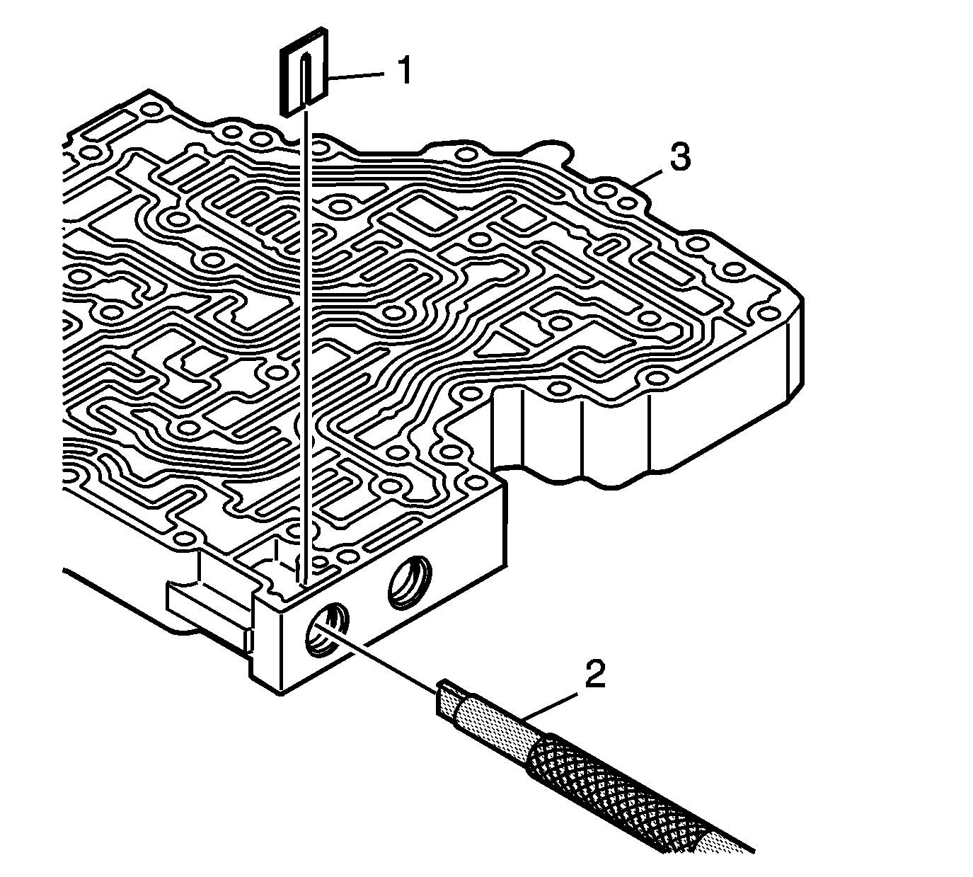
- Using
J 43773
(2), compress the control relief spring until the retaining clip (1) is loose. Remove the retaining clip (1).
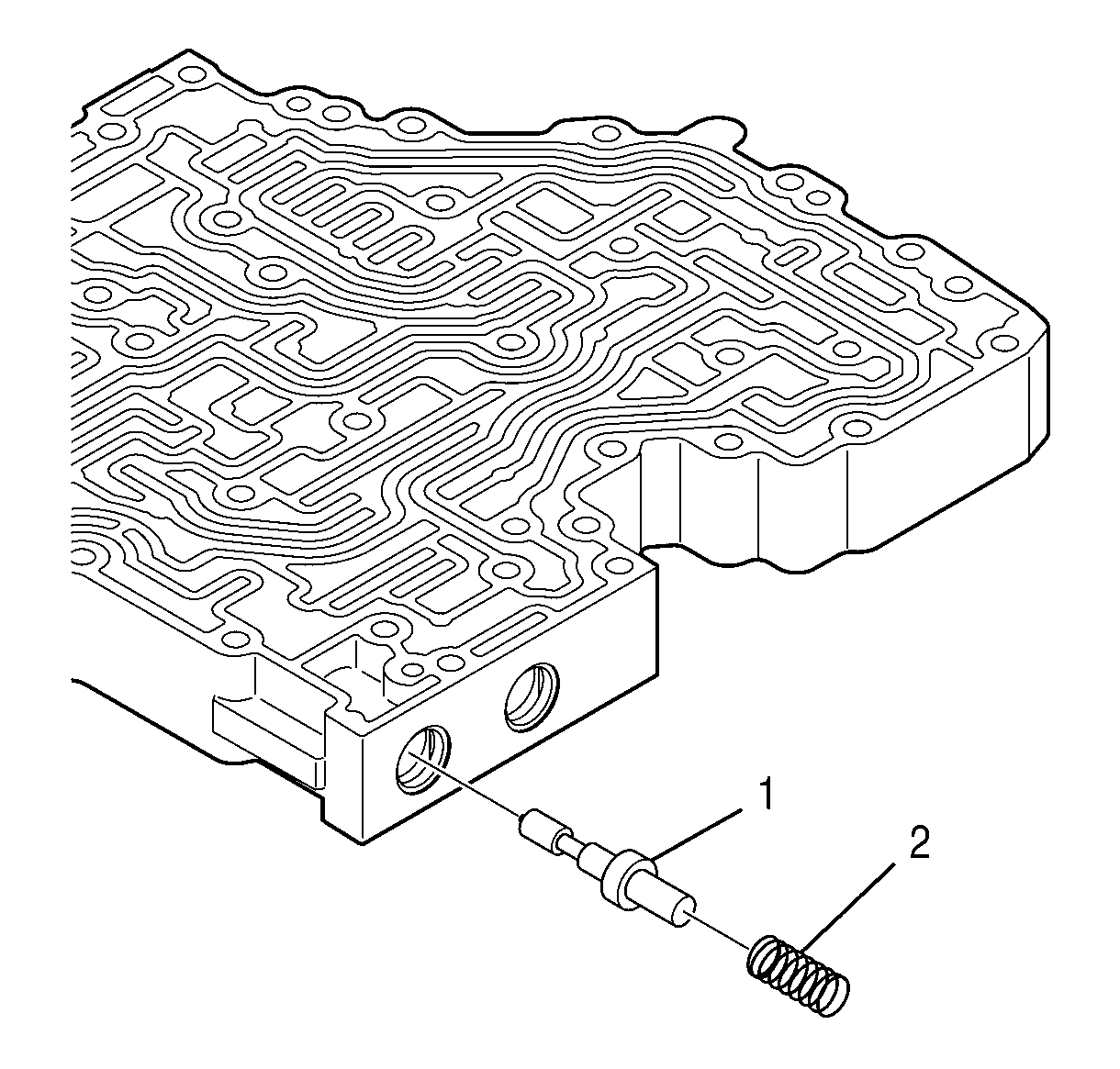
- Remove the spring (2) and the control relief valve (1).
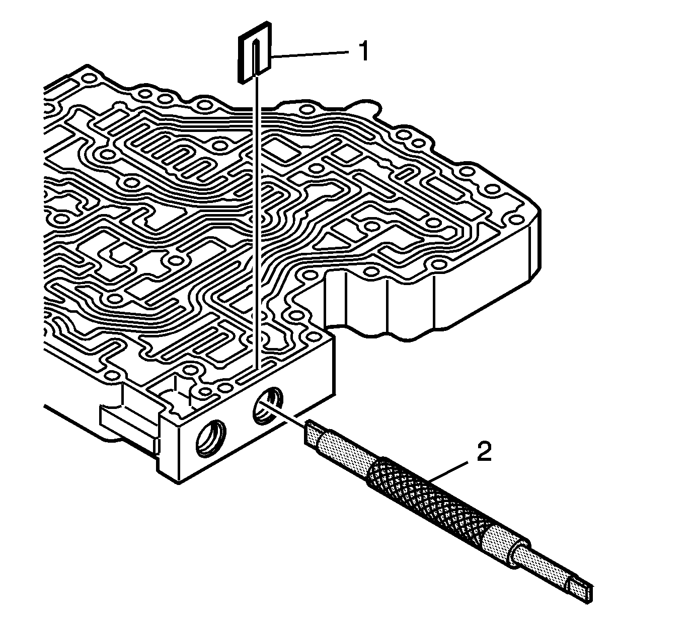
- Using
J 43773
, compress the exhaust backfill spring until the retaining clip (1) is loose. Remove the retaining clip (1).
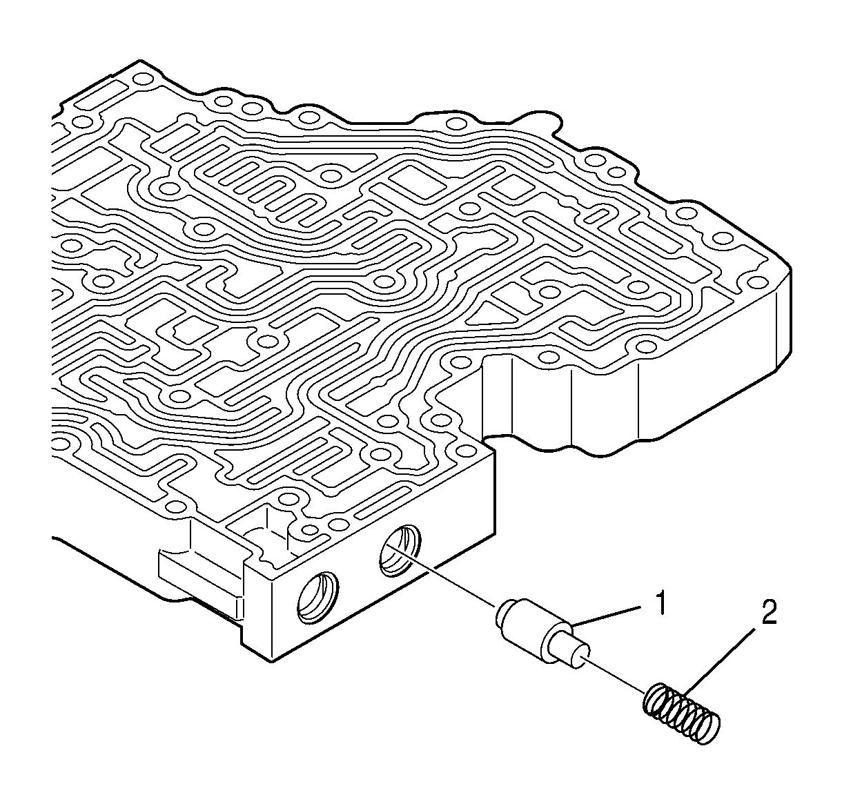
- Remove the spring (2) and the backfill exhaust valve (1).


