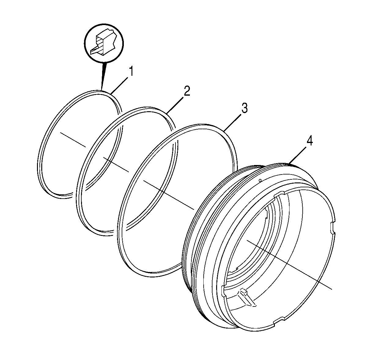
- Install the piston seal rings (1,
2, 3) onto the 4-5 clutch piston (4).
- Lubricate the 4-5 balance piston seal (3), the piston ID
and OD, and the seal rings (1, 2) with J 36850
®.
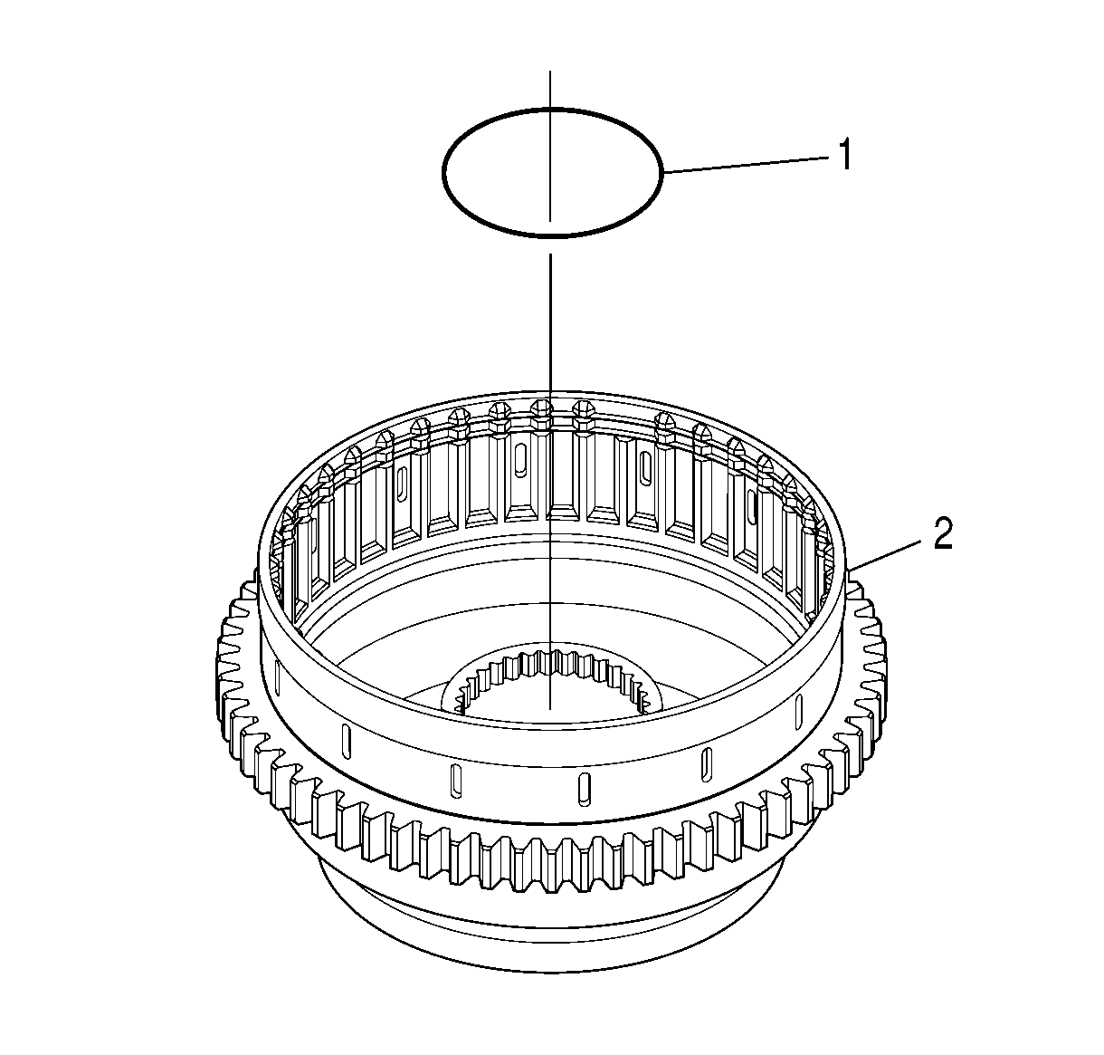
- Position
the 1-2-3-4, 4-5 clutch housing (2) on the work table
so that the rear of the housing is facing up.
- Install the O-ring (1) into the bottom groove on the inner hub
of the 1-2-3-4, 4-5 clutch housing (2).
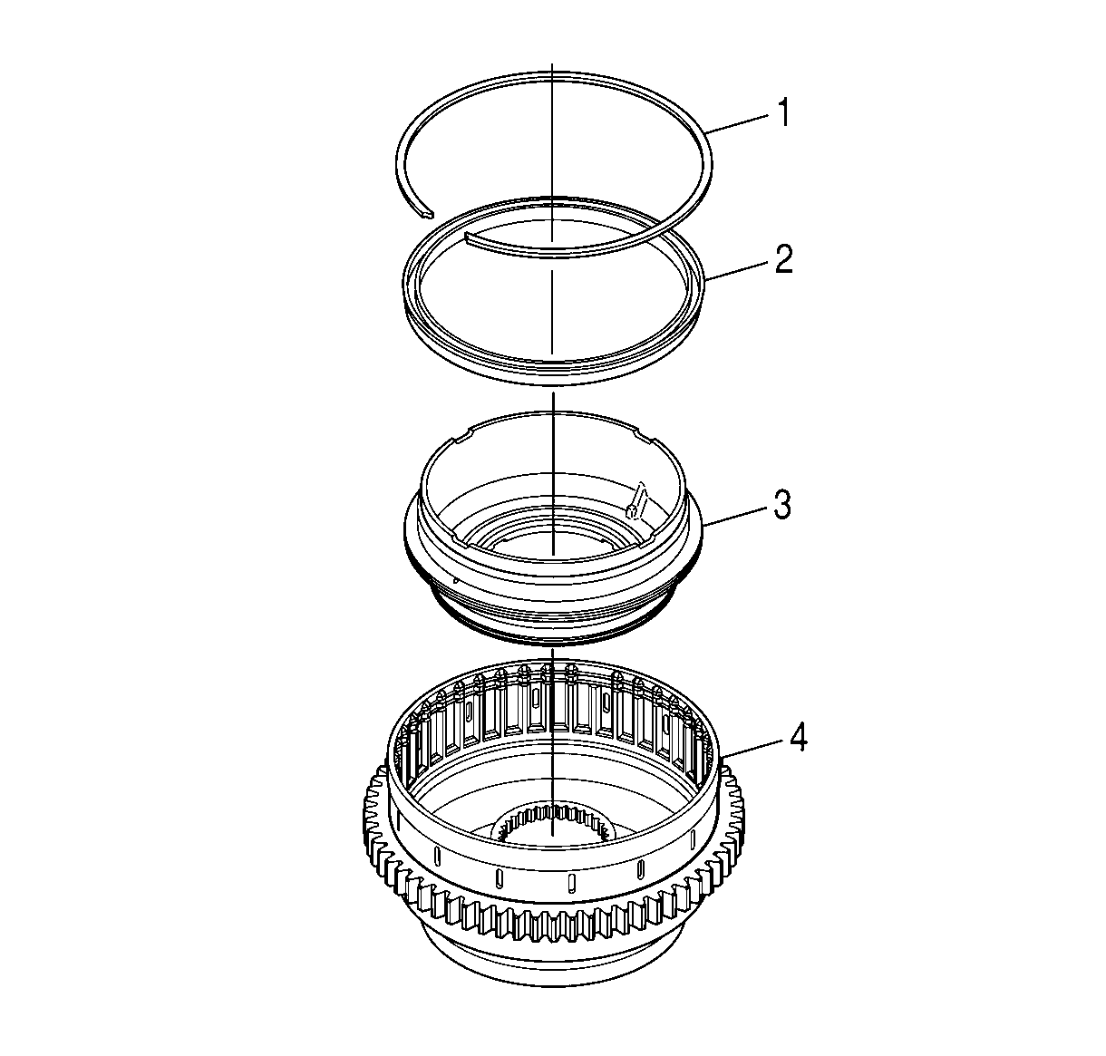
- Position the 4-5 clutch piston (3)
on the work table so that the rear of the piston is facing up.
- Align the 4-5 clutch balance piston (2) so that the rubber
seal is facing down.
- Install the 4-5 clutch balance piston (2) onto the 4-5
clutch piston (3).
- Lubricate the rubber seals on the 4-5 clutch balance piston (2)
with J 36850
®.
- Install the 4-5 clutch piston (3), with the 4-5 clutch
balance piston (2) attached, into the 1-2-3-4, 4-5
clutch housing (4).
- Make sure the 4-5 clutch piston (3) is seated on the 1-2-3-4,
4-5 clutch housing (4).
- Push the 4-5 clutch balance piston (2) below the retaining
ring groove on the 1-2-3-4, 4-5 clutch housing (4).
- Install the retaining ring (1) into the 1-2-3-4,
4-5 clutch housing (4).
- Make sure the retaining ring (1) is seated completely around the
1-2-3-4, 4-5 clutch housing (4).
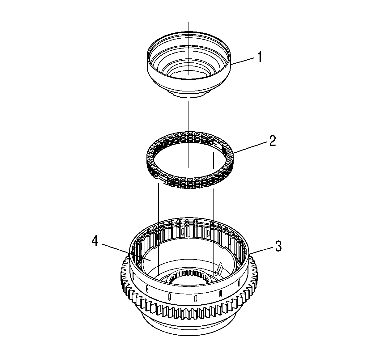
- Align the 4-5 clutch piston return
spring assembly (2) so that the notches of the spring assemblies are facing
and aligned with the tangs of the 4-5 clutch piston (4).
- Install the 4-5 clutch piston return spring assembly (2)
into the 4-5 clutch piston (4).
- Align the 1-2-3-4 clutch piston housing (1) so
that the rear of the housing is facing up.
- Install the 1-2-3-4 clutch piston housing (1)
into the 4-5 clutch piston (4).
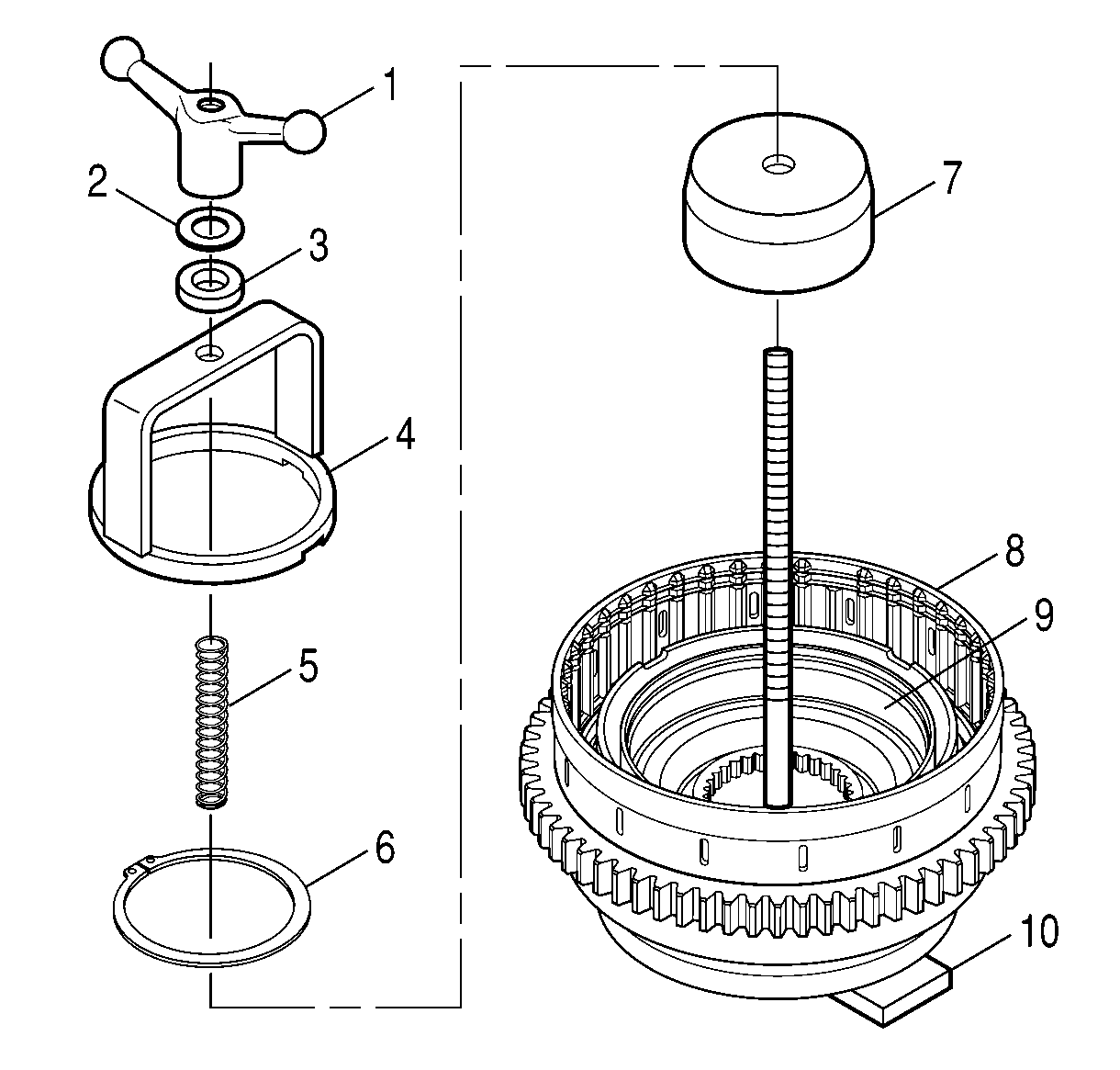
- Position the 1-2-3-4,
4-5 clutch housing (8) on the base of J 24204-2
(10) so that the rear of the housing is facing up.
- Install J 43776-1 (7) onto the shaft of J 24204-2
with the bowl down.
- Install the retaining ring (6) onto the surface of J 43776-2 (7).
- Install the spring (5) of J 43776
onto the shaft of J 24204-2
.
- Install J 43776-2 (4) onto the shaft of J 24204-2
.
- Align a notch of J 43776-2 (4) with the ball of the 1-2-3-4
clutch piston housing.
- Install the J 24204-2
ball
bearing (3) and washer (2) onto the shaft of J 24204-2
.
- Install the J 24204-2
wing nut (1) onto the shaft of J 24204-2
.
- Compress the 4-5 clutch piston return spring assembly until the
retaining ring groove on the inner hub of the 1-2-3-4, 4-5
clutch housing (8) is visible.
- Install the retaining ring (6) into the rotating clutch housing
inner hub.
- Make sure the retaining ring (6) is seated all around the clutch
housing (8).
- Remove all J tools except for the base of J 24204-2
.
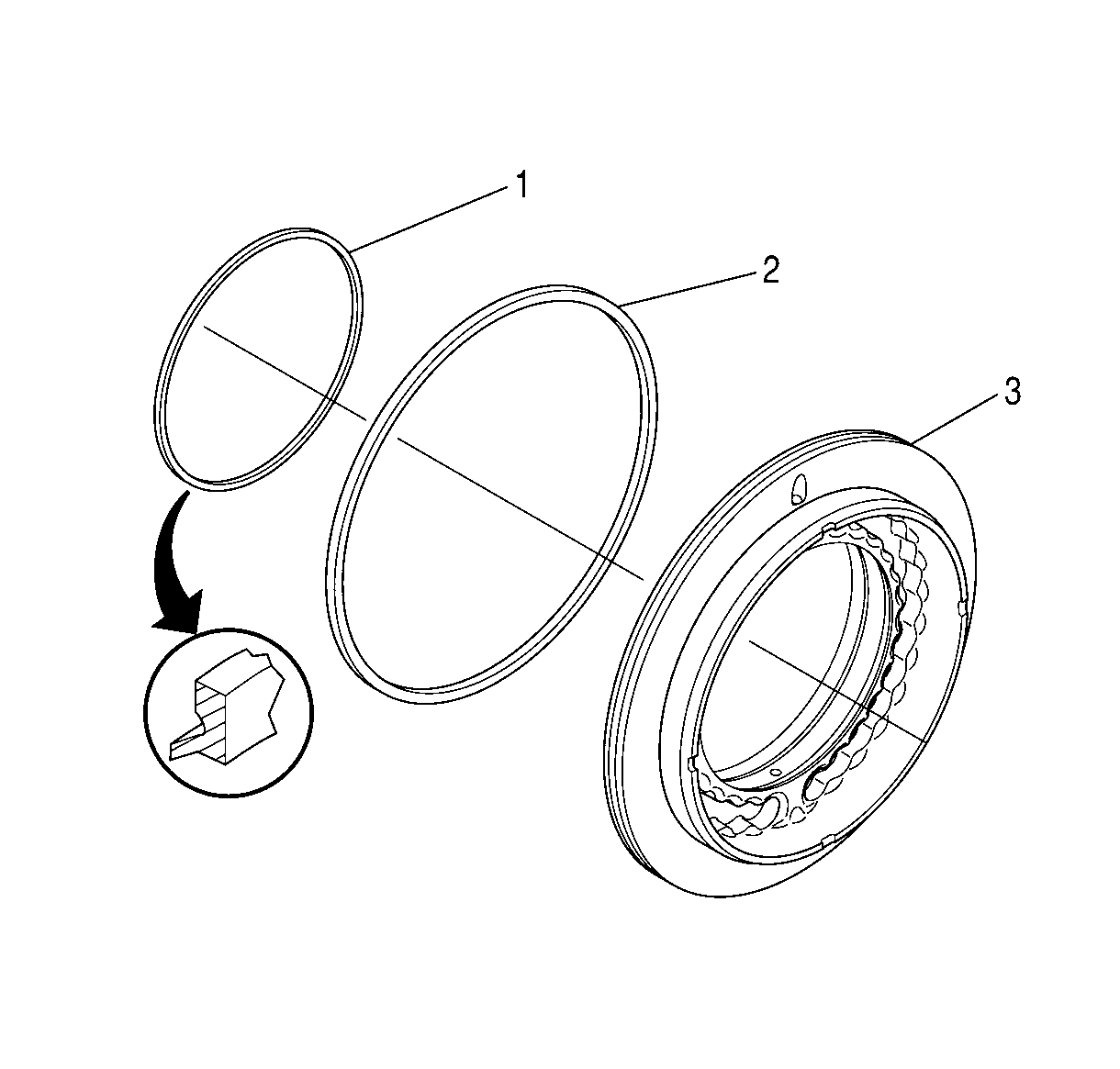
- Install the 1-2-3-4 clutch
piston ID seal ring (1) and the 1-2-3-4 clutch piston OD
seal ring (2) onto the 1-2-3-4 clutch piston (3).
- Lubricate the seal rings with J 36850
®.
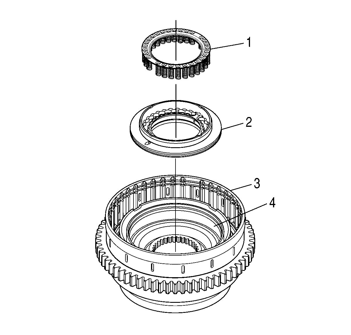
- Position the 1-2-3-4,
4-5 clutch housing (3) on the work table so that the rear of the housing
is facing up.
- Align the 1-2-3-4 clutch piston (2) so that the
spring indents are facing up.
- Install the 1-2-3-4 clutch piston (2) into the
1-2-3-4 clutch piston housing (4).
- Make sure the 1-2-3-4 clutch piston (2) is seated
in the 1-2-3-4 clutch piston housing (4).
- Align the 1-2-3-4 clutch piston return spring assembly (1)
so that the springs are facing and aligned with the spring pockets of 1-2-3-4
clutch piston (2).
- Install the 1-2-3-4 clutch piston return spring assembly (1)
into the 1-2-3-4 clutch piston (2).
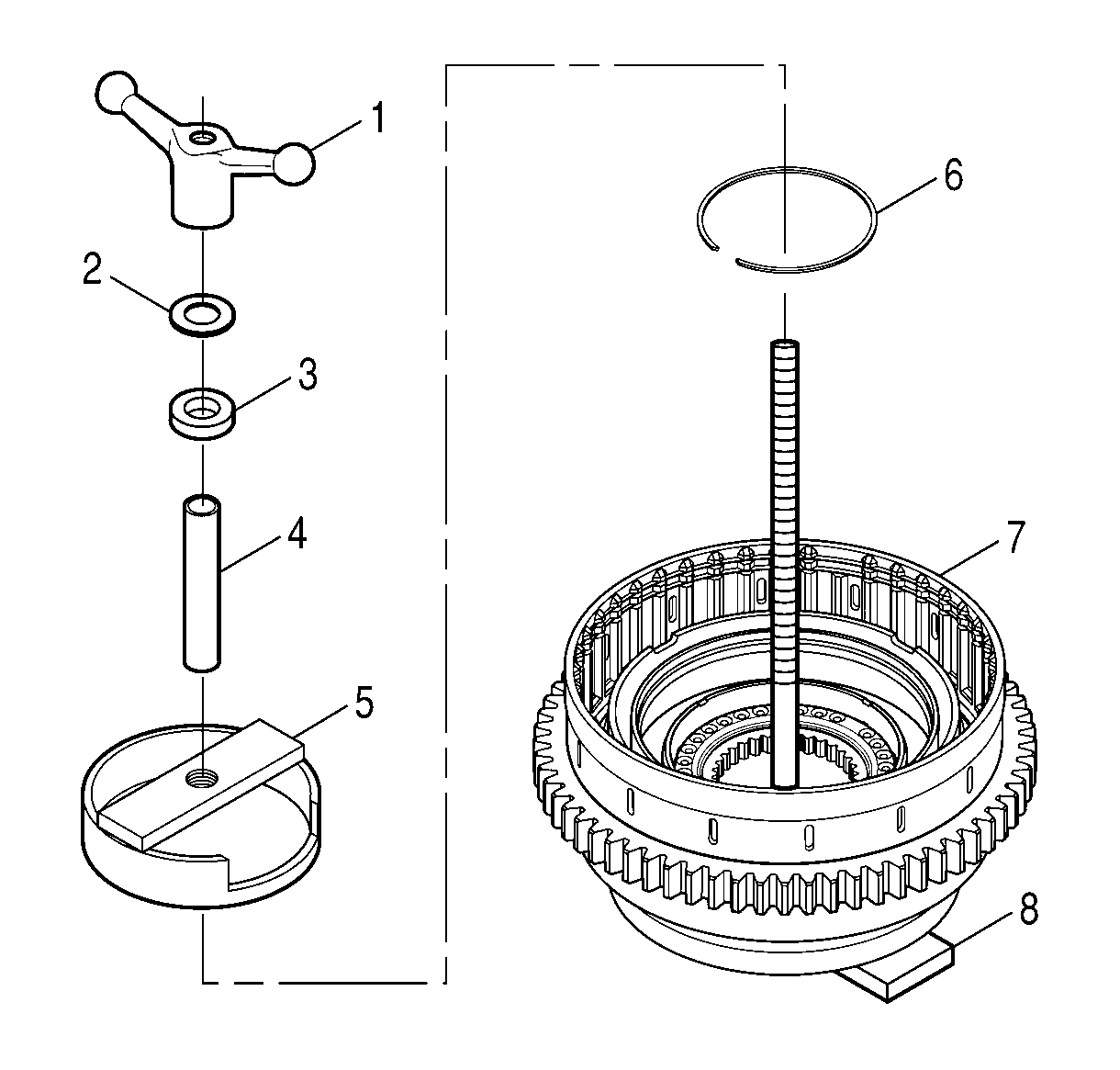
- Position the 1-2-3-4,
4-5 clutch housing (7) on the base of J 24204-2
(8) so that the rear of the housing is facing up.
- Install the retaining ring (6) into the inner hub of the 1-2-3-4,
4-5 clutch housing.
- Install J 43777
(5)
onto the shaft of J 24204-2
(8).
- Center J 43777
(5)
on the 1-2-3-4 clutch piston return spring assembly.
- Install the J 43777
extension (4) onto the shaft of J 24204-2
.
- Install the J 24204-2
ball bearing (3) and washer (2) onto the shaft of J 24204-2
.
- Install the J 24204-2
wing nut (1) on the shaft of J 24204-2
.
- Compress the 1-2-3-4 clutch piston return spring assembly
until the retaining ring groove on the 1-2-3-4, 4-5 clutch
housing inner hub is visible.
- Install the retaining ring (6) into the 1-2-3-4,
4-5 clutch housing inner hub.
- Remove tools J 24204-2
and J 43777
.
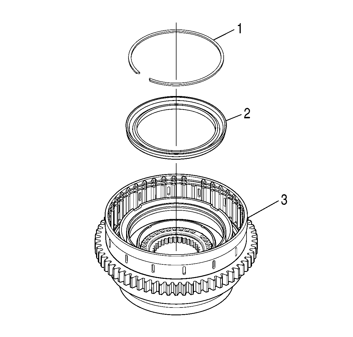
- Position the 1-2-3-4, 4-5 clutch housing (3)
on the work table so that the rear of the housing is facing up.
- Lubricate the rubber seals on the 1-2-3-4 clutch balance
piston (2) with J 36850
®.
- Align the 1-2-3-4 clutch balance piston (2) so
that the rubber seal is facing down.
- Install the 1-2-3-4 clutch balance piston (2)
between the 1-2-3-4 clutch piston and the 1-2-3-4
clutch piston housing.
- Press the 1-2-3-4 clutch balance piston (2) into
the 1-2-3-4 clutch piston housing until the 1-2-3-4
clutch balance piston is below the retaining ring groove on the 1-2-3-4
clutch piston housing.
- Install the retaining ring (1).
- Make sure the retaining ring (1) is seated in the groove.
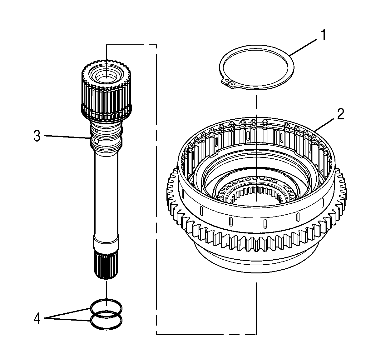
- Install 2 overlap seal rings (4)
onto the turbine shaft (3).
- Position the turbine shaft (3) on the work table so that the rear
of the shaft is facing up.
- Align the 1-2-3-4, 4-5 clutch housing (2)
with the rear of the turbine shaft (3) so that the rear of the clutch housing
is facing up.
- Install the 1-2-3-4, 4-5 clutch housing (2)
onto the rear of turbine shaft (3).
- Install the retaining ring (1) onto the turbine shaft (3).
- Make sure the retaining ring (1) is seated completely around the
turbine shaft (3).
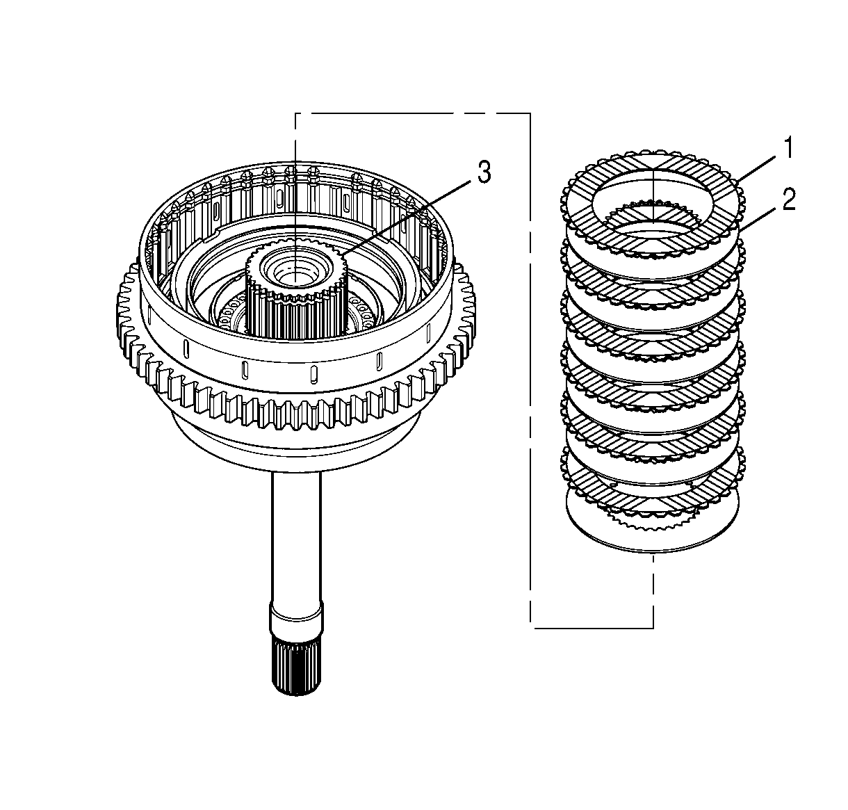
- Starting with a 1-2-3-4 clutch steel plate, alternately install
six 1-2-3-4 clutch steel plates (2) and six 1-2-3-4
clutch fiber plates (1) onto the turbine shaft (3).
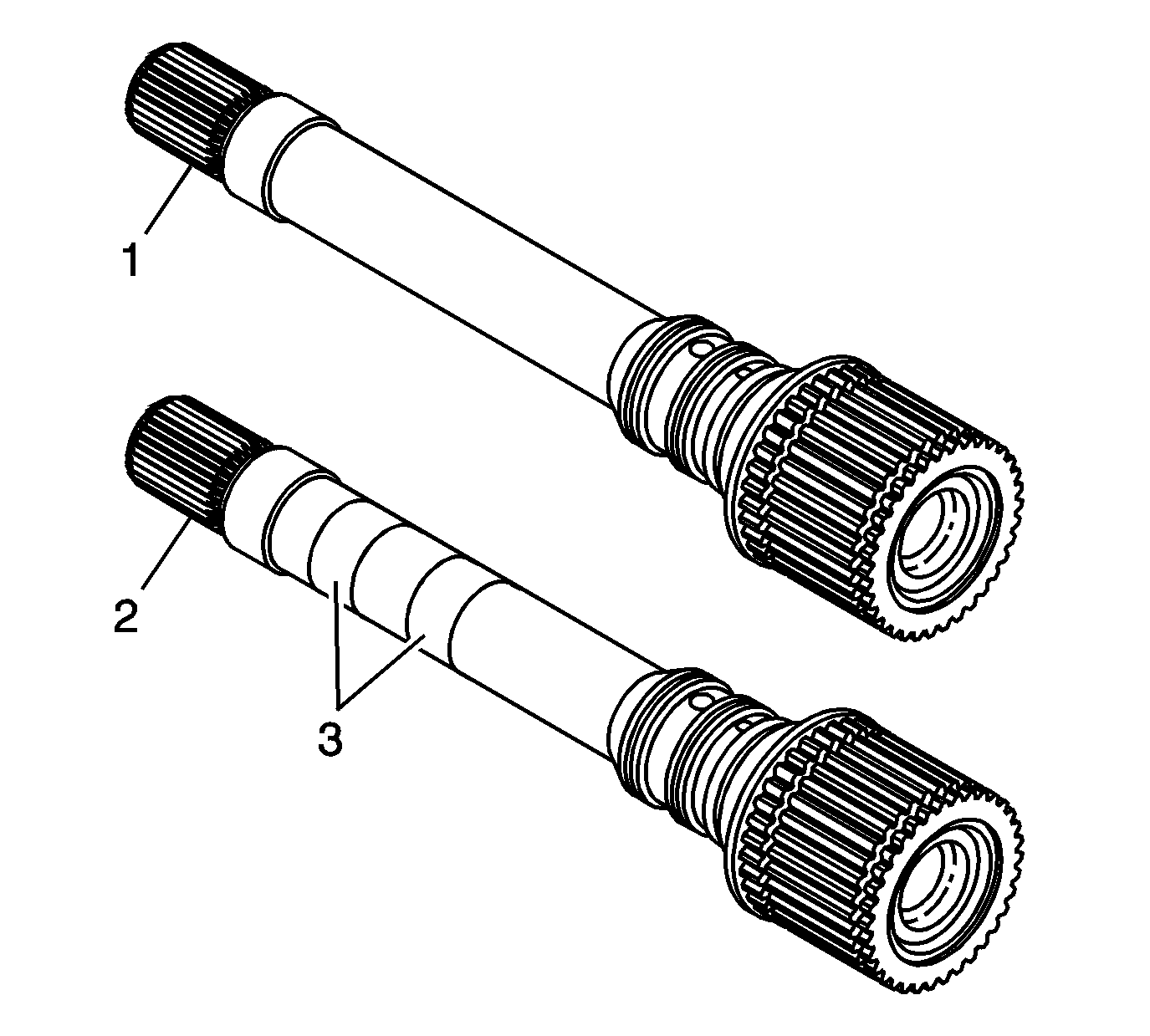
Important: There are 2 designs for the turbine shaft,
1-2-3-4 clutch hub, and the 1-2-3-4 clutch hub
thrust bearing. The current components are not interchangeable with the former components.
When replacing any one of the components with a current P/N in a former configuration,
it will require updating to the current design for all the parts.
- Determine which turbine shaft is being used in the transmission configuration.
The current design (2) will have a single or double identification mark (3)
on the shaft surface. The former design (1) will have a smooth shaft surface.
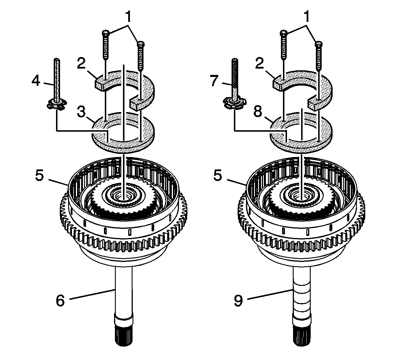
Important: Special tools J 44525-3 pressure plate (3)
and J 44525-2 selector tool (4) are black for easy identification, and used
with the former design. Special tools J 44525-4 selector tool (7) and J 44525-5
pressure plate (8) are silver plated for easy identification, and used with
the current design. Do not use the pressure plate and selector tool from the J 44525
set if they are not matched
in color.
- Align J 44525-3 pressure plate (3) or J 44525-5 pressure plate (8),
depending on model, with the turbine shaft so that the countersunk holes of J 44525-3
pressure plate (3) or J 44525-5 pressure plate (8) are facing up.
- Install J 44525-3 pressure plate (3) or J 44525-5 pressure plate (8)
onto the turbine shaft.
- Align J 44525-1 ridge plate (2) with the turbine shaft so that
the inner ridge of J 44525-1 ridge plate is facing down.
- Slide the inner ridge of J 44525 -1 ridge plate (2) into the turbine
shaft retaining ring groove.
- Align the holes in J 44525-1 ridge plate (2) with the countersunk
holes of J 44525-3 pressure plate (3) or J 44525-5 pressure plate (8).
Notice: Refer to Fastener Notice in the Preface section.
- Hand install 2 bolts (1) of J 44525
into the holes of J 44525-1 ridge plate (2).
Tighten
Tighten the bolts to 1.8 N·m (16 lb in).
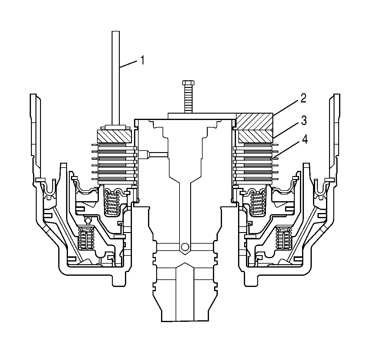
Important: The shift quality of the transmission depends
heavily upon selecting the correct 1-2-3-4 clutch backing plate.
- Perform the following procedure for each tab of J 44525-2 selector tool (1)
or J 44525-4 selector tool (1):
| 69.1. | Place the flat surface, tabbed end of J 44525-2 selector tool (1)
or J 44525-4 selector tool (1) onto the top surface of J 44525-3 pressure plate (3)
or J 44525-5 pressure plate (3). |
| | Important: At most, 2 of the different tabs will
fit into the retaining ring groove.
|
| 69.2. | Try to slide the tabbed end of J 44525-2 selector tool (1) or J
44525-4 selector tool (1) into the retaining ring groove on the turbine shaft. |
| 69.3. | If a tab fits into the retaining ring groove, record the 4-digit ID number
located on the stem of J 44525-2 selector tool (1) that is associated with
the tab or on the tab of J 44525-4 selector tool (1). Refer to
Selective Components Specifications
to determine the
correct backing plate. |
- Select a 1-2-3-4 clutch backing plate as follows:
| • | For the former design, if no tab of J 44525-2 selector tool (1)
fits into the retaining ring groove, select the 1-2-3-4 clutch backing
plate with ID No. 6221 or 8521. |
| • | For the current design,
if no tab of J 44525-4 selector tool (1) fits into the retaining ring groove,
select the 1-2-3-4 clutch backing plate with ID No. 2420. |
| • | If one or more tabs of J 44525-2 selector tool (1) or J 44525-4
selector tool (1) fit into the retaining ring groove, select the 1-2-3-4
clutch backing plate with an ID No. corresponding to the highest number recorded
in the previous step. |
- Remove J 44525
from the turbine shaft.
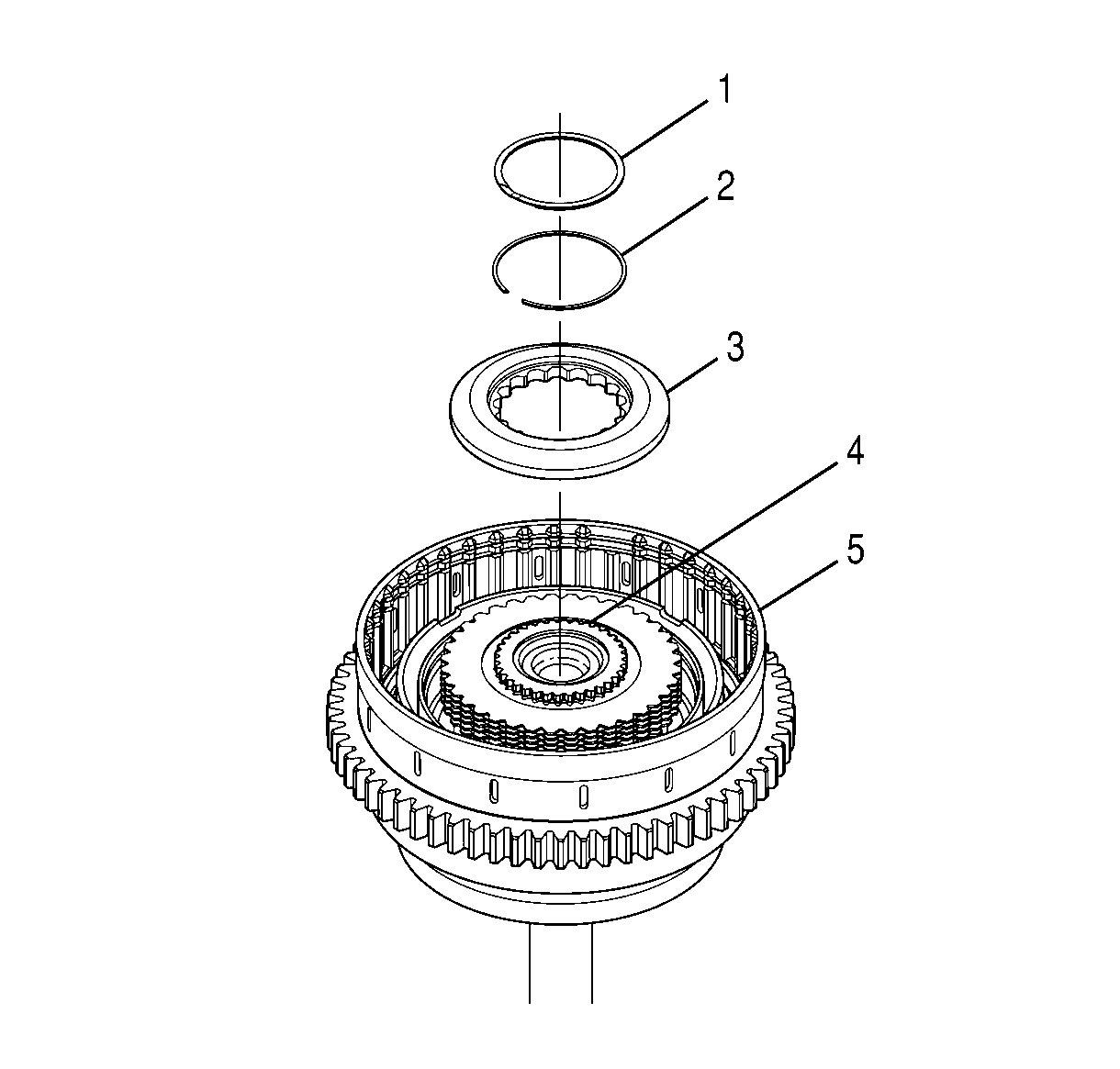
- Align the selected 1-2-3-4
clutch backing plate (3) so that the beveled edge of the backing plate is facing
up.
- Install the 1-2-3-4 clutch backing plate (3)
onto the turbine shaft (4).
- Install the retaining ring (2) onto the turbine shaft (4).
- Lift the 1-2-3-4 clutch backing plate (3) and
install the spiral retaining ring (1) into the 1-2-3-4 clutch
backing plate (3).
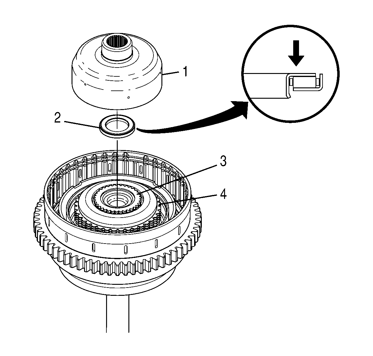
Notice: Installing
the thrust bearing assembly onto the rear of the turbine shaft in the wrong direction
may cause permanent damage to the transmission. The blue stripe must be visible.
Important: There are 2 designs for the turbine shaft,
1-2-3-4 clutch hub, and the 1-2-3-4 clutch hub
thrust bearing. The current components are not interchangeable with the former components.
When replacing any one of the components with a current P/N in a former configuration,
it will require updating to the current design for all the parts.
- Align thrust bearing assembly (2) so that the blue stripe on the thrust
bearing assembly is facing away from turbine shaft (3).
- Install the thrust bearing assembly (2) into the turbine shaft (3).
- Make sure the blue stripe on the thrust bearing assembly is visible.
- Center the 1-2-3-4 clutch plates (4).
- Install the 1-2-3-4 clutch drive hub (1) over
the 1-2-3-4 clutch plates (4).
- Make sure the 1-2-3-4 clutch drive hub (1) has
seated on the thrust bearing assembly (2).
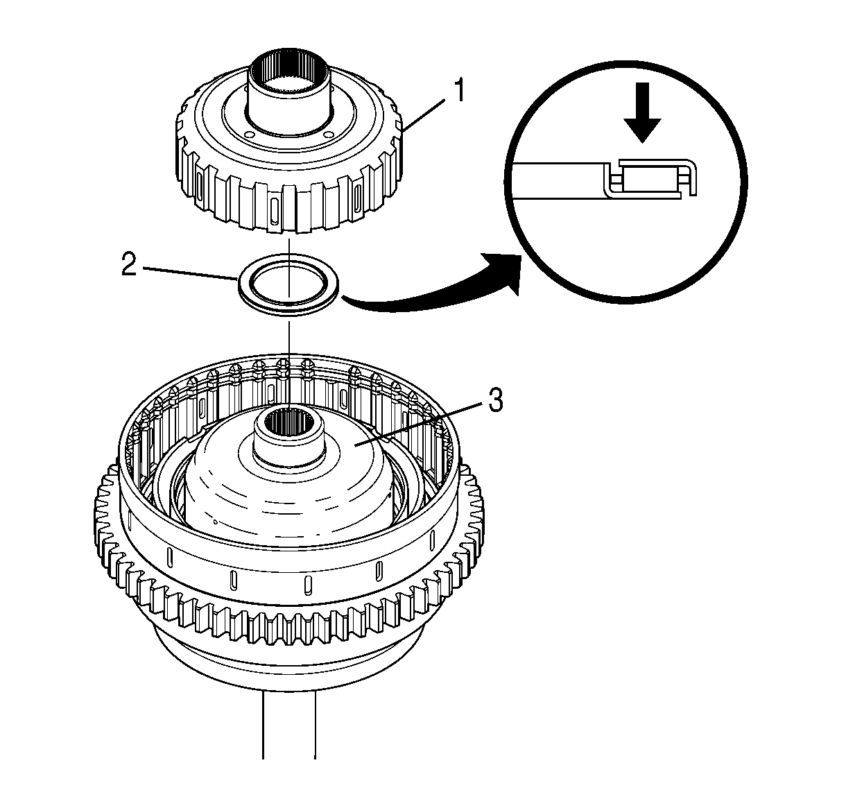
Notice: Installing the thrust bearing assembly onto the rear of
the 1-2-3-4 drive hub in the wrong direction may cause permanent
damage to the transmission. The blue stripe must be visible.
- Align the thrust bearing assembly (2) so that the blue stripe on the
thrust bearing assembly is facing away from the 1-2-3-4 clutch drive
hub (3).
- Install the thrust bearing assembly (2) onto the rear of the 1-2-3-4
clutch drive hub (3).
- Make sure the blue stripe on the thrust bearing assembly is visible.
- Align the 4-5 clutch drive hub (1) so that the smaller end
is facing up.
- Install the 4-5 clutch drive hub (1).
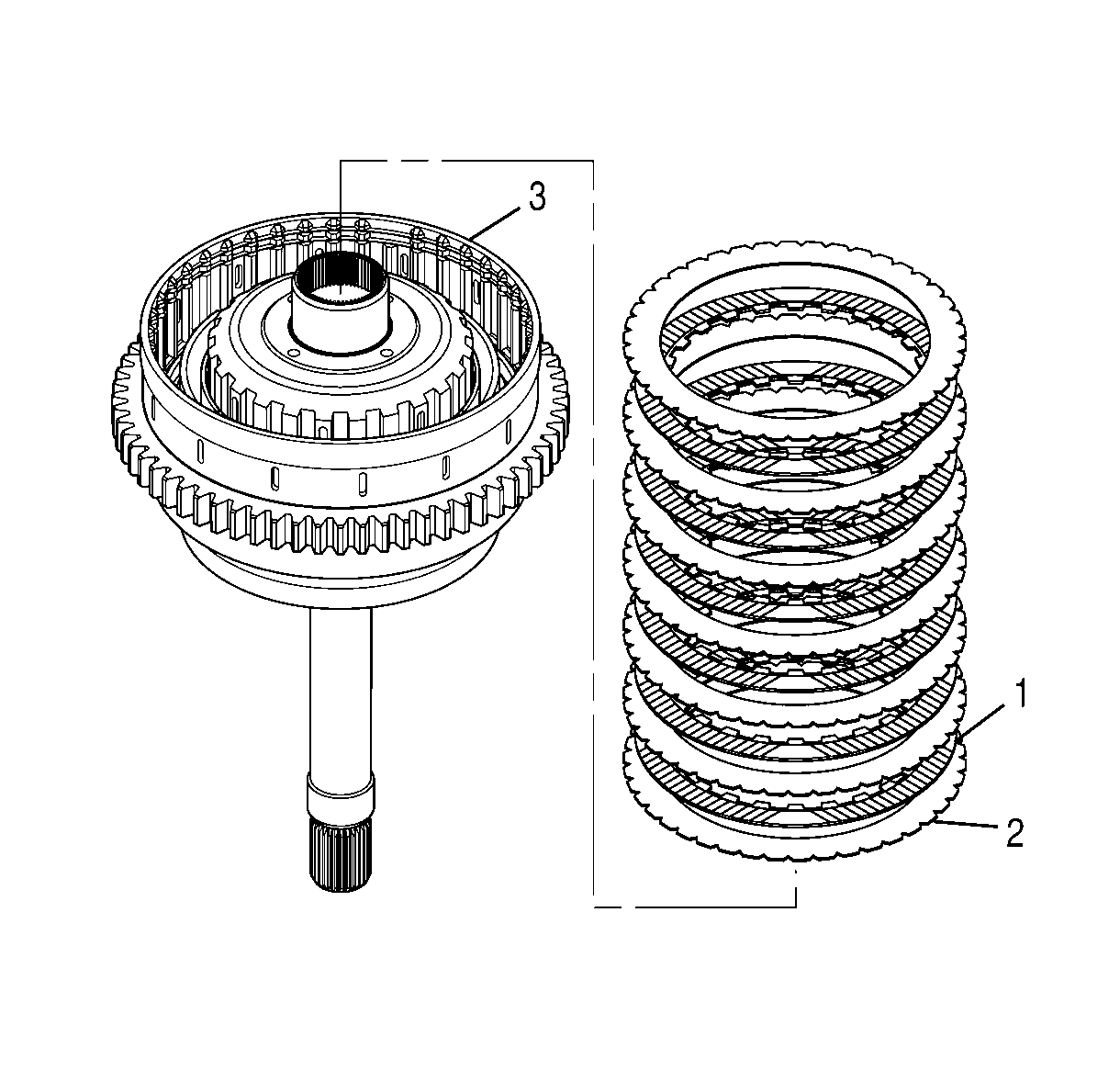
- Starting with a 4-5 clutch steel plate, alternately install seven 4-5
clutch steel plates (2) and six 4-5 clutch fiber plates (1) into
the 1-2-3-4, 4-5 clutch housing.
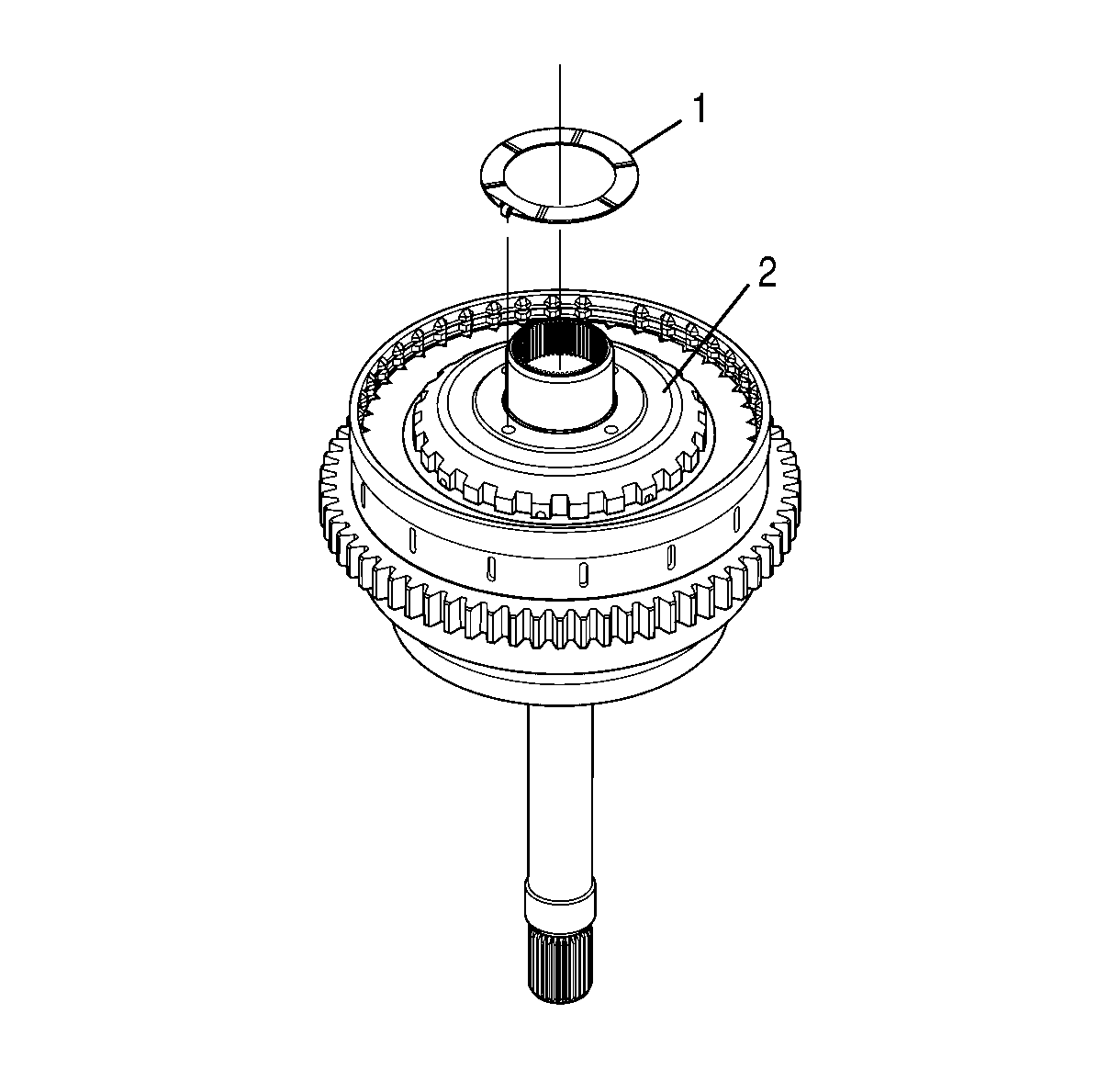
- Align the tangs of the bronze thrust washer (1)
with the holes in the 4-5 clutch drive hub (2).
- Install the bronze thrust washer (1) onto the 4-5 clutch
drive hub (2).
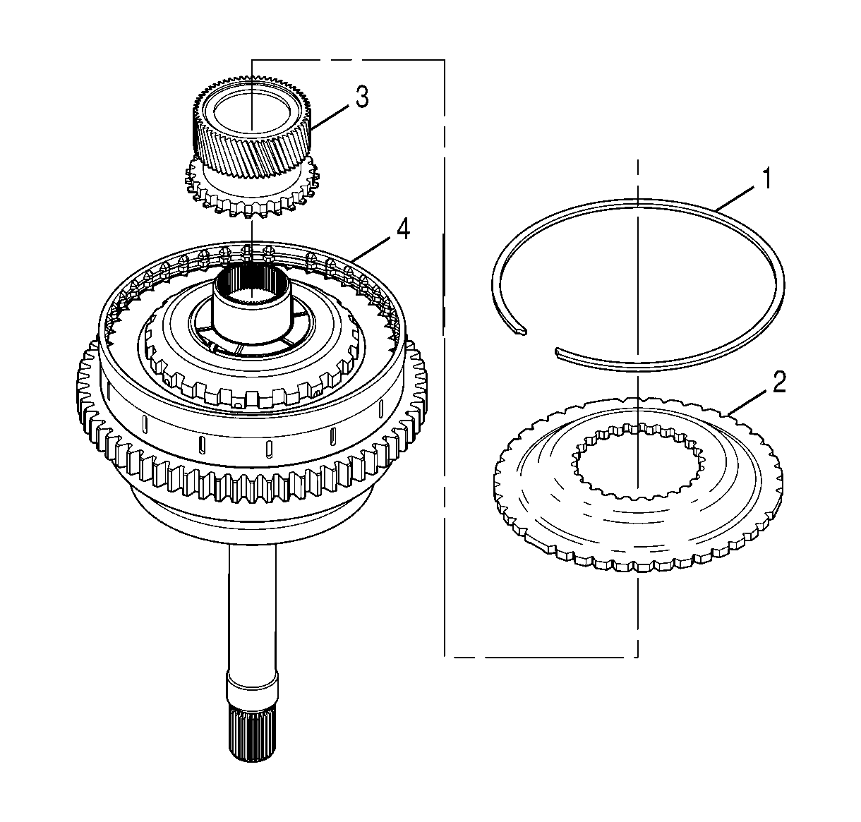
- Align the input sun gear (3) so that
the gear teeth of the sun gear face the concave face of the input sun gear flange (2).
- Install the input sun gear (3) into the input sun gear flange (2).
- Make sure the splines are engaged.
- Hold the sun gear and align the double wide splines of the input sun gear
flange (2) with the double wide spaces on the 1-2-3-4, 4-5
clutch housing (4).
- Install the input sun gear (3) with the input sun gear flange (2)
into the 1-2-3-4, 4-5 clutch housing (4).
- Install the input sun gear external retaining ring (1) into the
1-2-3-4, 4-5 clutch housing (4).
- Make sure the retaining ring is seated all the way around the 1-2-3-4,
4-5 clutch housing.
- Remove tools J 24204-2
and J 43777
.


