ALTITUDE ADJUSTMENTS MADE FROM LOW TO HIGH ALTITUDE

General Motors did not offer an Altitude Emissions Package as an option for the 1981 model year. Instead, the Environmental Protection Agency has approved certain adjustments on 1981 passenger vehicles built and certified for operation at low altitudes but delivered by dealers located at 4,000 foot altitudes or higher.
The approval of these adjustments is STRICTLY LIMITED TO THOSE DEALERSHIPS LOCATED AT ALTITUDES OF 4,000 FEET OR HIGHER, IN COUNTIES DESIGNATED BY EPA AS HIGH ALTITUDE COUNTIES FOR THE 1977 MODEL YEAR.
ALTITUDE ADJUSTMENT LABEL
When LOW ALTITUDE vehicles (Federal or California) are adjusted for high altitude operation, a SUPPLEMENTAL emission control information label must be placed next to the existing underhood emission control information label. Wash off the area with soap and water, dry thoroughly, and apply the new label.
ALTITUDE ADJUSTMENT LABEL
Supplemental Vehicle Emission Control Information Label, in kit part number 22513965 with the legend DIESEL PROCEDURE must be installed. Refer to the installation instructions covered previously in this bulletin.
PARTS INFORMATION
A kit is available through WDDGM part number 22513965.
Kit Contents Part Number 22513965 Quantity
Locknut 1 Seal 1 Metering Valve Screw 1 Instruction Sheet 1 Label 1
HANDLING OF ALTITUDE ADJUSTMENT EXPENSE
1. Predelivery - to be performed at time of predelivery by those dealers in designated high altitude counties or by designated fringe area dealers delivering a vehicle to an owner residing in a designated high altitude county.
High altitude adjustments labor and parts will automatically be credited to dealers in designated high altitude counties on the 921 card as determined by the VIN engine code designation.
Dealers in fringe area counties are to submit a warranty claim when performing the pre-delivery high altitude adjustments on vehicles purchased for use in high altitudes. Claims should be submitted as a parts and labor claim with part count 1, failed part 22513965 using trouble code 92. This allowance must be authorized by a GMC representative prior to submission.
2. Owners who live in a high altitude county and have taken delivery of a 1981 Diesel Engine Equipped GMC truck prior to this bulletin - Dealers in designated high altitude or fringe area counties are to encourage owners to have the high altitude adjustment performed. Such adjustments performed on all 1981 GMC trucks are to be submitted as a warranty claim. The claim will require zone authorization.
3. Owners who move to high altitude counties - dealers in high altitude areas should encourage owners who have moved to high altitude counties to purchase this adjustment service which is considered an owner maintenance expense.
4. Owners who move from high altitude counties - dealers must advise owners moving to low altitude areas that the engine must be readjusted to "Low Altitude" configuration by removing the metering valve stop screw and reinstalling the pressure tap plug and removing the high altitude label. This is considered an owner maintenance expense.
DEALER AND CUSTOMER INFORMATION
Dealers located at 4,000 foot elevations or higher, in counties designated by EPA as high altitude counties for the 1977 model year, should perform these adjustments prior to delivery of a new 1981 vehicle to the customer. Owners of 1981 low altitude vehicles, purchased in low altitude areas, taking up permanent residence in one of these high altitude counties should be encouraged to have these adjustments performed when vehicles are brought in for service.
After performing these adjustments, dealers must advise customers that, IF THE VEHICLE IS RETURNED TO CONTINUOUS, LOW ALTITUDE OPERATION, THE ENGINE MUST BE RE-ADJUSTED TO LOW ALTITUDE.
SPECIALTOOLS REQUIRED
All tools or equipment required to perform these adjustments are presented in detail in GMC Light Duty Truck Service Manuals and include the following:
- intake air crossover screen J-26996-2 - magnetic tachometer J-26925
1981 INJECTION PUMP PROCEDURE FOR CONVERSION TO HIGH ALTITUDE APPLICATION:
1. Set idle speeds to specification.
2. With engine off but at normal operating temperature, transmission in park and air conditioner off, remove air cleaner and air crossover.
3. Cap intake manifold with screen covers.
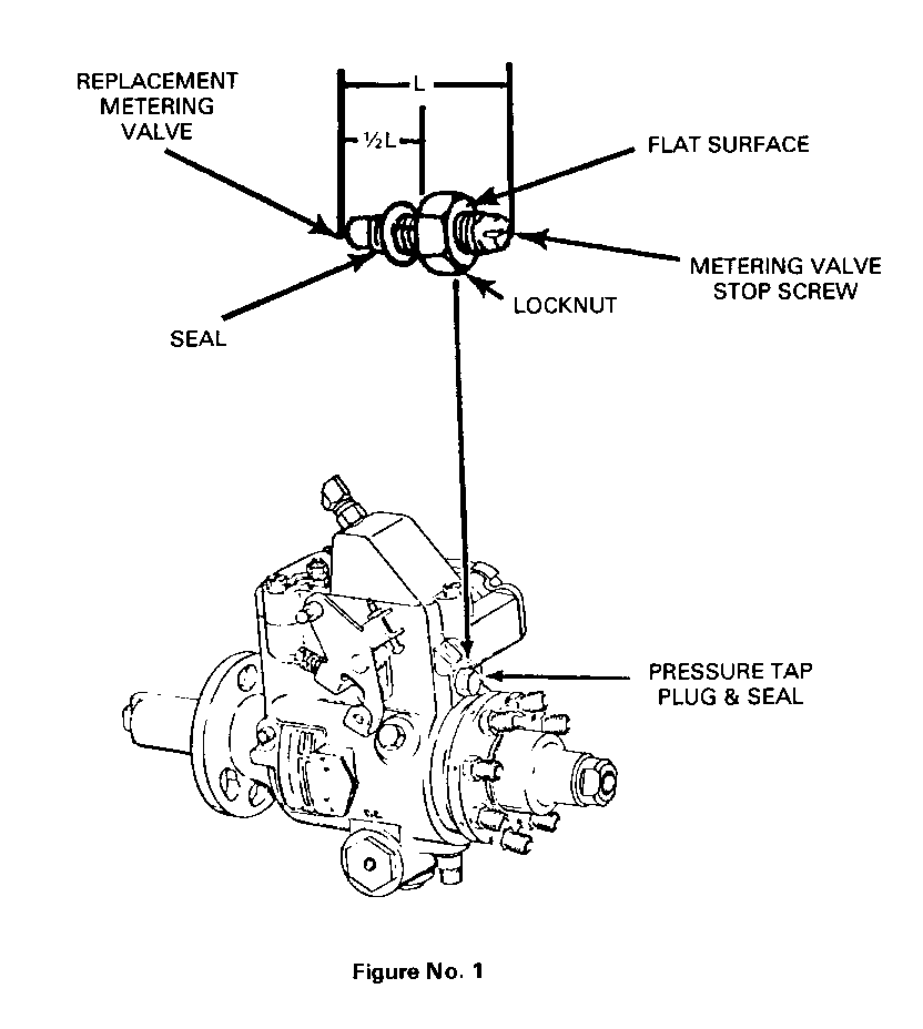
4. Remove pressure tap plug and seal located on the rear of the pump (Figure No. 1).
5. Assemble locknut and new seal to metering valve stop screw as shown.
6. Install assembly in injection pump until locknut contacts pump housing. Tighten locknut.
7. Insert probe of (J-26925) magnetic pick-up tachometer in timing indicator hole and start engine.
8. Loosen locknut and slowly turn metering valve stop screw clockwise until idle speed drops approximately 10 RPM.
9. Turn metering valve stop screw counterclock-wise 1-1/2 turns and tighten locknut.
10. Check installation for fuel leaks.
11. Turn engine off.
12. Remove magnetic tachometer probe and screened covers from intake manifold and reinstall parts removed.

General Motors bulletins are intended for use by professional technicians, not a "do-it-yourselfer". They are written to inform those technicians of conditions that may occur on some vehicles, or to provide information that could assist in the proper service of a vehicle. Properly trained technicians have the equipment, tools, safety instructions and know-how to do a job properly and safely. If a condition is described, do not assume that the bulletin applies to your vehicle, or that your vehicle will have that condition. See a General Motors dealer servicing your brand of General Motors vehicle for information on whether your vehicle may benefit from the information.
