INOP INTER. SWING-OUT DOOR REPLACE LOCK ROD ASSY.

SUBJECT: INOPERATIVE INTERMEDIATE SWING-OUT DOOR (REPLACE LOCK ROD CLIP)
VEHICLES AFFECTED: 1986-91 G VANS WITH RPO E24
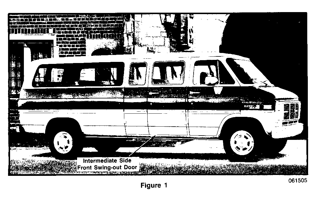
Some of the above model vehicles may experience an inoperative intermediate side front swing-out door, as shown in Figure 1. The operator may find it difficult to open the subject door from the inside of the vehicle. This condition can occur if the inside handle rod disengages from the door lock assembly.
To correct, it is necessary to replace the inside handle rod clip with a new style clip (P/N 3962782) and modify one end of the inside handle rod. The original clip is made out of blue nylon material. The new clip is black and made out of spring steel.
REMOVAL AND REPLACEMENT INSTRUCTIONS (Figures 2-3)
1. Disconnect the battery negative cable.
2. Open the door from the outside.
NOTE: IF THE VEHICLE IS EQUIPPED WITH A DOOR TRIM PANEL, THE PULL STRAP AND TRIM PANEL MUST BE REMOVED FIRST TO GAIN ACCESS TO COMPONENT PARTS.
IF THE VEHICLE IS NOT EQUIPPED WITH A DOOR TRIM PANEL, PROCEED WITH THE FOLLOWING STEPS:
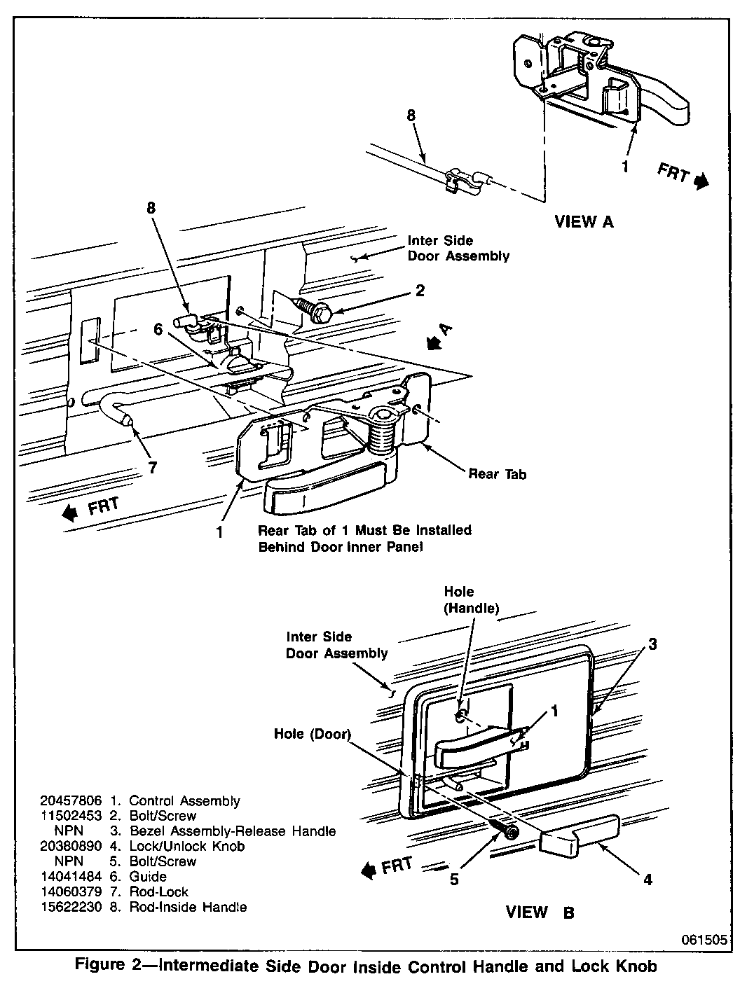
3. Remove two screws from the release handle bezel assembly, (Figure 2, View B, 3 and 5.) Carefully disengage the sliding remote lock/unlock knob (4) from the lock rod. Remove the knob and release handle bezel assembly.
4. Remove one attaching screw from the door control assembly (interior release handle assembly) and disengage from the inside handle rod (Figure 2, View A, 1 and 8). The rod may already be disengaged from the assembly. If the inside handle rod is disengaged, retrieve it from the door assembly.
When the inside handle rod is still secured on the control assembly, use a counterclockwise motion to disengage the control assembly from the inside handle rod.
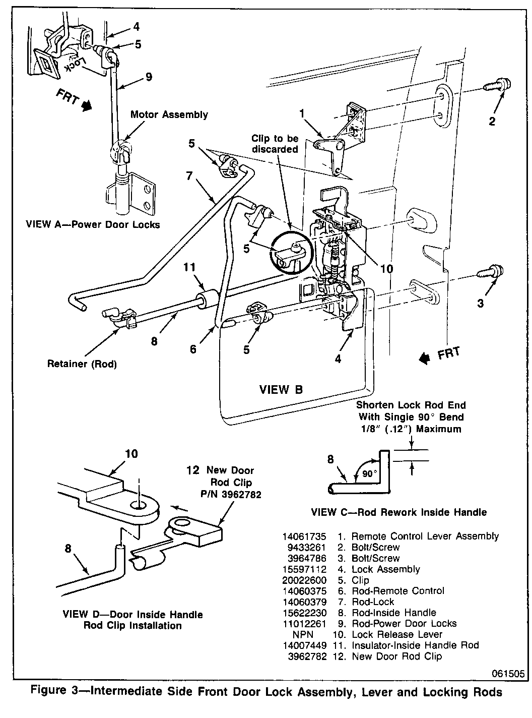
5. Remove approximately 1/8" (.12") maximum material using a saw or grinder from the end of the inside handle rod with the single 90 degree bend (Figure 3, View C).
6. Remove the door lock assembly by unfastening three mounting screws. (Figure 3, View B, 3 and 4).
7. Refer to Figure 3, View B and disconnect the remote control upper rod (6) from the lock assembly (4). If the vehicle is equipped with power door locks, disconnect the power door lock rod (Figure 3, View A, 9) from the door lock assembly (4).
8. Remove and discard the blue nylon clip (Item 5) from the door lock release lever (Figure 3, 5 and 10).
9. Install and position insulator (P/N 14007449), (Figure 3, Item 11 approximately in the centre of the inside handle rod.
10. Align holes of new spring steel clip (P/N 3962782) (Figure 3, View D, 12) over the lock release lever hole. Install modified inside handle rod end (90 degree bend) through both holes of the new clip and lock release lever hole. Insert from bottom up. Snap inside handle rod into retaining portion of the new clip (Figure 3, View D).
11. Carefully insert lock assembly (with inside handle rod attached) through door access hole. Reattach lock assembly to door. Torque mounting fasteners to 25-40 N.m (18-30 ft.lbs.).
12. Refer to Figure 3 (Views A and B) and reconnect the upper rod (6) and power door lock rod (9), if equipped, to the lock assembly (4).
13. Reinstall the control assembly (Figure 2, View B, 1) to inside handle rod and door. Torque control assembly mounting fastener, 1 to 1-1/2 N.m (10-14 in.lbs.). Check for proper operation, correct as necessary. If the inside handle rod rattles, reposition inside handle rod insulator (11) to eliminate condition.
14. If the vehicle is equipped with a door trim panel, reinstall the trim panel and pull strap.
15. Reinstall the bezel assembly to the door and insert the lock rod into the sliding remote lock/unlock knob. Torque the fasteners to 1 to 1-1/2 N.m (10-14 in.lbs.).
16. Check for proper door lock operation, make any corrections as required.
17. Reconnect the battery negative cable.
SERVICE PARTS INFORMATION ---------------------------- Quantity Description Part Number Required --------------------- ----------- -------- Spring Steel Clip 3962782 1
Inside Handle Rod 14007449 1 Insulator
Use the most applicable Labour Operation and Time from the Canadian Labour Time guide.


General Motors bulletins are intended for use by professional technicians, not a "do-it-yourselfer". They are written to inform those technicians of conditions that may occur on some vehicles, or to provide information that could assist in the proper service of a vehicle. Properly trained technicians have the equipment, tools, safety instructions and know-how to do a job properly and safely. If a condition is described, do not assume that the bulletin applies to your vehicle, or that your vehicle will have that condition. See a General Motors dealer servicing your brand of General Motors vehicle for information on whether your vehicle may benefit from the information.
