OVER EXTENSION OF FRT. SHOCKS NEW TORSION BAR ADJUSTER

MODELS: 1988-1989 K1, K2, K3 TRUCKS WITH F60 (HEAVY DUTY FRONT SPRINGS)
A 1990 model torsion bar adjusting arm (Part # 15603963) is now available through GMSPO for 1988 and 1989 model trucks equipped with F-60 option that continue to damage front shocks, even after adjusting the torsion bar for the lowest front ride height. This new torsion bar adjusting arm will provide a lower front ride height, thus preventing over extension and damage to shocks. These adjusters will not change Gross Front Axle Weight Rating (GFAWR).
SERVICE PROCEDURE:
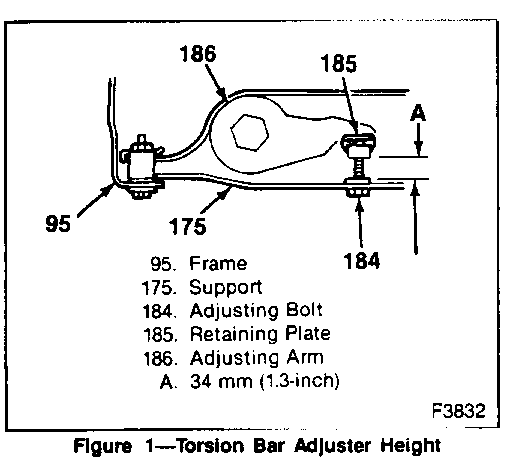
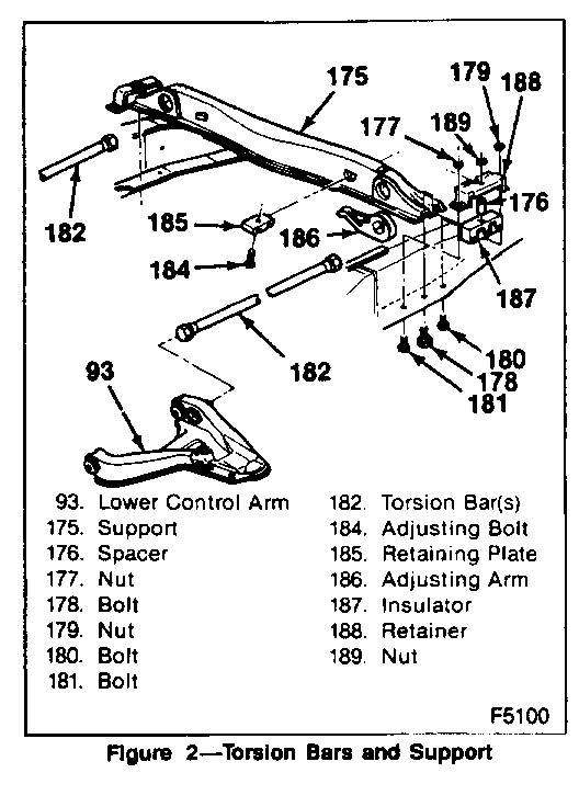
Removal Procedufe For Torsion Bar Adjustment Assemblies On Both Tomion Bars (See Figures 1 And 2).
Tool Required:
J 36202 - Torsion Bar Unloading Tool
1. Raise vehicle front and support with suitable safety stands.
2. Increase the tension on adjustment arm (186) using J 36202.
3. Remove adjustment bolt (184) and retaining plate (185).
4. Release tension on adjustment arm and move tool aside.
5. Slide torsion bars forward.
6. Remove the adjustment arms (186).
Replacement Procedure For New Torsion Bar Adjustment Assemblies On Both Torsion Bars (See Figures 1 And 2).
Tool Required:
J 36202 - Torsion Bar Unloading Tool
1. Fit the new torsion bar adjusting arms (Part # 15603963) on the torsion bars.
2. Increase the tension on the torsion bar, using J 36202.
3. Install the retaining plate and the adjustment bolt.
4. Release the tension on the torsion bar until the load is taken up by the adjustment bolt.
5. Remove J 36202.
6. Lower the vehicle.
7. Reset "Z" height and front end alignment to the specifications listed at the end of this bulletin.
SERVICE PARTS INFORMATION:
Part Number Description Qty
15603963 Torsion Bar Adjuster 2 (currently available at GMSPO)
WARRANTY INFORMATION:
For repairs under warranty use:
Labor Operation: T8130 Replace both torsion bar adjuster arms, set "Z" height, and check front wheel alignment.
Labor Time: .9 hr.
Add: To Align Front Wheels
-K Trucks without cam kits previously installed. 1.2 hrs.
-K Trucks with cam kits previously installed. .6 h rs
NOTE: Labor operation is coded to base vehicle coverage in the warranty system.
SERVICE SPECIFICATIONS
After installing these adjusters the Z height setting and alignment specifications should be reset to the revised 1990 specifications listed below:
TRIM HEIGHTS (Z HEIGHTS)
Model Z Height
K1, K2-C6P 157.0 m, +/- 6.0 mm K2+C6P, K3 145.0 mm +/- 6.0 mm
ALIGNMENT SPECIFICATIONS (K1, 2, 3)
Model Camber Cross Camber
K1, K2-C6P 0.65 degrees 0.5 degrees +/- 0.5 degrees
K2+C6P, K3 0.50 degrees 0.5 degrees 0.5 degrees
Model Caster Cross Caster
3.00 degrees K 1, 2, 3 1.00 degrees 0.5 degrees
Model Total Toe
K 1, 2, 3 +.24 degrees +/- 0.2 degrees (+.1.25 in. +/- 0.1 in.) Steering wheel angle is +/- 5.0 deg
Document shown below should be produced locally and provided to the owners of vehicles modified by this repair procedure.
THIS VEHICLE HAS BEEN EQUIPPED WITH 1990 MODELTORSION BAR ADJUSTERS
ANY RESETTING OF FRONT END ALIGNMENT OR VEHICLE TRIM HEIGHT (Z-HEIGHT) SHOULD CONFORM TO THE REVISED 1990 SPECIFICATIONS LISTED BELOW.
TRIM HEIGHTS (Z HEIGHTS)
Model Z Height
K1, K2-C6P 157.0 mm +/- 6.0 mm K2+C6P, K3 145.0 mm +/- 6.0 mm
ALIGNMENT SPECIFICATIONS (K1, 2, 3)
Model Camber Cross Camber K1, K2-C6P 0.65 degrees 0.5 degrees +/- 0.5 degrees
K2+C6P, K3 0.50 degrees 0.5 degrees +/- 0.5 degrees
Model Caster Cross Caster
K1, 2, 3 3.00 degrees 0.5 degrees 1.00 degrees
Model Total Toe
K1, 2, 3 +.24 degrees +/- 0.2 degrees (+.125 in. +/- 0.1 in.)
Steering wheel angle is +/- 5.0 degrees


General Motors bulletins are intended for use by professional technicians, not a "do-it-yourselfer". They are written to inform those technicians of conditions that may occur on some vehicles, or to provide information that could assist in the proper service of a vehicle. Properly trained technicians have the equipment, tools, safety instructions and know-how to do a job properly and safely. If a condition is described, do not assume that the bulletin applies to your vehicle, or that your vehicle will have that condition. See a General Motors dealer servicing your brand of General Motors vehicle for information on whether your vehicle may benefit from the information.
