SQUEAK WHILE TURNING AND/OR MORE FREQUENT STEERING INPUT

GREASEABLE UPPER & LOWER CONTROL ARM BALL JOINTS AND FRONT END ALIGNMENT PARTS KIT
Models: 1988 - 1990 C/K Trucks
TO ALL GENERAL MOTORS DEALERS:
THIS BULLETIN CANCELS AND REPLACES GM SPECIAL POLICY BULLETIN OS02A DATED JANUARY, 1991 TO REVISE THE SERVICE PROCEDURE AND THE LABOUR TIMES. ALL COPIES OF OS02A SHOULD BE DISCARDED.
REVISIONS TO THIS BULLETIN INCLUDE ADDITION OF A REQUIREMENT TO CHECK THE CONDITION OF 1990 MODEL YEAR C/K MAINTENANCE-FREE BALL JOINTS BEFORE REPLACEMENT, ELIMINATION OF CASTER/CAMBER ALIGNMENT AND ADDITION OF TOE-IN ALIGNMENT.
Ball Joints:
A contaminated front suspension ball joint can cause squeaking while turning and/or require more frequent steering input while driving down the road. Contamination could also cause a ball joint to wear out and eventually to separate.
1988-1989
Some of the maintenance-free front suspension ball joints used on 1988 and 1989 model C/K trucks have experienced contamination.
1990
Later design maintenance-free ball joints were used in early 1990 model C truck front suspension upper control arms and K truck front suspension upper and lower control arms. Those maintenance-free front suspension ball joints used in the 1990 model C/K trucks incorporated two significant design changes that greatly reduce the possibility of contamination.
- An enhancement was made at the neck of the ball stud by changing the material of the seal insert to glass-filled nylon for greater stiffness and less shrinkage when cold.
In addition, the composition of the seal was changed to make it more flexible in cold weather.
Since the first publication of the Special Policy Adjustment Bulletin, stringent lab testing, proving ground durability tests and a fleet field test have demonstrated the durability of the 1990 model C/K maintenance-free front suspension ball joints. Therefore, to determine whether a customer complaint is attributable to contamination of a maintenance-free ball joint on a 1990 model truck, do not replace any such ball joint unless the ball joint wear check included in this bulletin indicates over 1 mm (0.040 inch) of lash.
Greaseable ball joints were also used in 1990 model year production as follows since:
- start of production on the C truck front suspension lower control arms;
- interim production on the C truck front suspension upper control arms; and
- interim production on the K truck front suspension upper and lower control arms.
The greaseable style ball joint incorporates a zerk fitting to facilitate maintenance and is designed to allow grease to purge at die interface of the rubber dust cover and the ball joint shell (or socket).
Replacement Ball Joints
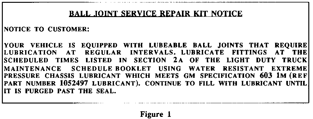
Greaseable ball joints should be used as replacements for contaminated maintenance-free ball joints. Since it is important to lubricate the greaseable ball joint, customers must be given the information slip, shown in figure 1, which explains the greaseable ball joint maintenance requirements. This slip is packaged in each service ball joint kit.
BALL JOINT SERVICE REPAIR KIT NOTICE
NOTICE TO CUSTOMER:
YOUR VEHICLE IS EQUIPPED WITH LUBEABLE BALL JOINTS THAT REQUIRE LUBRICATION AT REGULAR INTERVALS. LUBRICATE FITTINGS AT THE SCHEDULED TIMES LISTED IN SECTION 2A OF THE LIGHT DUTY TRUCK MAINTENANCE SCHEDULE BOOKLET USING WATER RESISTANT EXTREME PRESSURE CHASSIS LUBRICANT WHICH MEETS GM SPECIFICATION 603 1M (REF PART NUMBER 1052497 LUBRICANT). CONTINUE TO FILL WITH LUBRICANT UNTIL IT IS PURGED PAST THE SEAL.
Front Wheel Caster/Camber-Alignment Parts Kit: ---------------------------------------------- The 1988-90 C/K Trucks incorporate a front suspension feature designed to improve the vehicle's ability to maintain front wheel caster/camber alignment. The front wheel alignment set by the assembly plant will not change and should not need adjustment except in cases where accident or road hazard damage has occurred. Through the listed VIN breakpoints, in customer pay situation, if caster/camber alignment was performed, the customer was also charged for the required alignment parts kit. Due to the cost of the parts kit, the charge for a wheel alignment would not be competitive in today's marketplace. In view of this, General Motors of Canada has issued a special policy to cover the cost of the caster/camber alignment parts kit but not the installation cost. This kit is included in vehicles currently being produced.
GMC VEHICLES INVOLVED
YEAR MODEL PLANT FROM THROUGH COMPONENTS INVOLVED ---- ----- ----- ---- ------- ------------------- 1988 C/K Ft. Wayne SOP EOP All Ball Joints 1988 C/K Oshawa SOP EOP All Ball Joints 1988 C/K Pontiac SOP EOP All Ball Joints 1989 C/K Ft. Wayne SOP EOP All Ball Joints 1989 C/K Oshawa SOP EOP All Ball Joints 1989 C/K Pontiac SOP EOP All Ball Joints 1990 C Ft. Wayne SOP LZ531411 Upper Ball Joints 1990 K Ft. Wayne SOP LZ532770 All Ball Joints 1990 C Oshawa SOP L1539478 Upper Ball Joints 1990 K Oshawa SOP L1539477 All Ball Joints 1990 C Pontiac SOP LE530629 Upper Ball Joints 1990 K Pontiac SOP LE530628 All Ball Joints 1988 C/K Ft. Wayne SOP EOP Alignment Parts Kit 1988 C/K Oshawa SOP EOP Alignment Parts Kit 1988 C/K Pontiac SOP EOP Alignment Parts Kit 1989 C/K Ft. Wayne SOP EOP Alignment Parts Kit 1989 C/K Oshawa SOP EOP Alignment Parts Kit 1989 C/K Pontiac SOP EOP Alignment Parts Kit 1990 C/K Ft. Wayne SOP LZ525988 Alignment Parts Kit 1990 C/K Oshawa SOP L1536879 Alignment Parts Kit 1990 C/K Pontiac SOP LE530905 Alignment Parts Kit
CHEVROLET VEHICLES INVOLVED
YEAR MODEL PLANT FROM THROUGH COMPONENTS INVOLVED ---- ----- ----- ---- ------- ------------------- 1988 C/K Ft. Wayne SOP EOP All Ball Joints 1988 C/K Oshawa SOP EOP All Ball Joints 1988 C/K Pontiac SOP EOP All Ball Joints 1989 C/K Ft. Wayne SOP EOP All Ball Joints 1989 C/K Oshawa SOP EOP All Ball Joints 1989 C/K Pontiac SOP EOP All Ball Joints 1990 C Ft. Wayne SOP LZ205050 Upper Ball Joints 1990 K Ft. Wayne SOP LZ209446 All Ball Joints 1990 C Oshawa SOP L1198892 Upper Ball Joints 1990 K Oshawa SOP L1198892 All Ball Joints 1990 C Pontiac SOP LE187809 All Ball Joints 1990 K Pontiac SOP LE187809 All Ball Joints 1988 C/K Ft. Wayne SOP EOP Alignment Parts Kit 1988 C/K Oshawa SOP EOP Alignment Parts Kit 1988 C/K Pontiac SOP EOP Alignment Parts Kit 1989 C/K Ft. Wayne SOP EOP Alignment Parts Kit 1989 C/K Oshawa SOP EOP Alignment Parts Kit 1989 C/K Pontiac SOP EOP Alignment Parts Kit 1990 C/K Ft. Wayne SOP LZ181940 Alignment Parts Kit 1990 C/K Oshawa SOP L1186255 Alignment Parts Kit 1990 C/K Pontiac SOP LE196361 Alignment Parts Kit
SPECIAL POLICY ADJUSTMENT
Ball Joints:
On 1988, 1989 and 1990 models up to the VIN breakpoints, for a period of 5 years or 160,000 km from the original in-service date, whichever occurs first, if a customer experiences contamination of any of the maintenance-free ball joints, all maintenance-free ball joints will be replaced with greaseable ball joints at no charge ($ 100.00 deductible does not apply). However, there is a reduced likelihood that a 1990 model truck complaint of squeaking while turning, more frequent steering input while driving down the road or a symptom that a maintenance-free ball joint might be wearing out is attributable to a contaminated maintenance-free ball joint due to the improved performance of 1990 model year maintenance-free ball joints. For 1990 model trucks only, conduct the ball joint wear check included in this Bulletin to determine whether a customer complaint is attributable to contamination of a maintenance-free ball joint. Do not replace the maintenance-free ball joints in a 1990 model truck unless a ball joint check indicates over 1 mm (0.040 inch) of lash. Additionally, the customer may be eligible for reimbursement for previous repairs with supporting documentation.
Field testing has now confirmed that a 1988-90 C/K truck does not require front wheel alignment due to ball joint replacement. Therefore, caster/camber alignment will no longer be provided upon customer request under this special policy. However, in the interest of customer satisfaction and upon customer request, a toe-in alignment may be completed after the maintenance-free ball joint replacement is done under this special policy.
Front Wheel Caster/Camber Alienment Parts Kit: ---------------------------------------------- On 1988, 1989 and 1990 models up to the VIN breakpoints, for a period of 5 years or 160,000 km from the original in-service date, whichever occurs first, if a customer's vehicle requires caster/ camber alignment, the caster/camber alignment parts kit will be provided at no charge (but not the installation cost). Testing has confirmed that caster/camber alignment is only required due to accident or Toad hazard damage.
OWNER NOTIFICATION:
Owners of 1988 and 1989 vehicles involved in this SPECIAL POLICY ADJUSTMENT have been notified by General Motors of Canada (see copy of owner letter included with this bulletin). Owners of 1990 vehicles involved in this SPECIAL POLICY ADJUSTMENT are well within the warranty period and will not be sent an owner letter at this time.
Ball Joint Wear Check (1990 Only)
The following checking procedures apply to 1990 K Model upper and lower ball joints and 1990 C Model upper ball joints only. (1990 C Models have greaseable lower ball joints).
1990 K Model Lower
- Be sure the vehicle rests on a level surface.
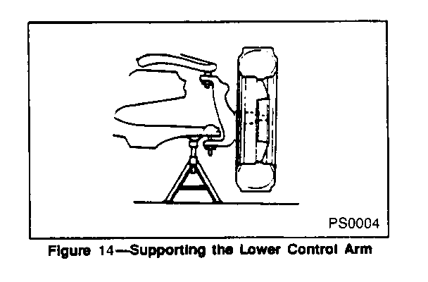
- Raise and support front of vehicle with suitable safety stands. Support the lower control and with a floor stand or jack as far outboard as possible.
- The vehicle must be stable and should not rock on the floor stands.
- If the vehicle is equipped with aluminum wheels it may be necessary to first remove the wheel.
Check the Ball Joints for Vertical Looseness
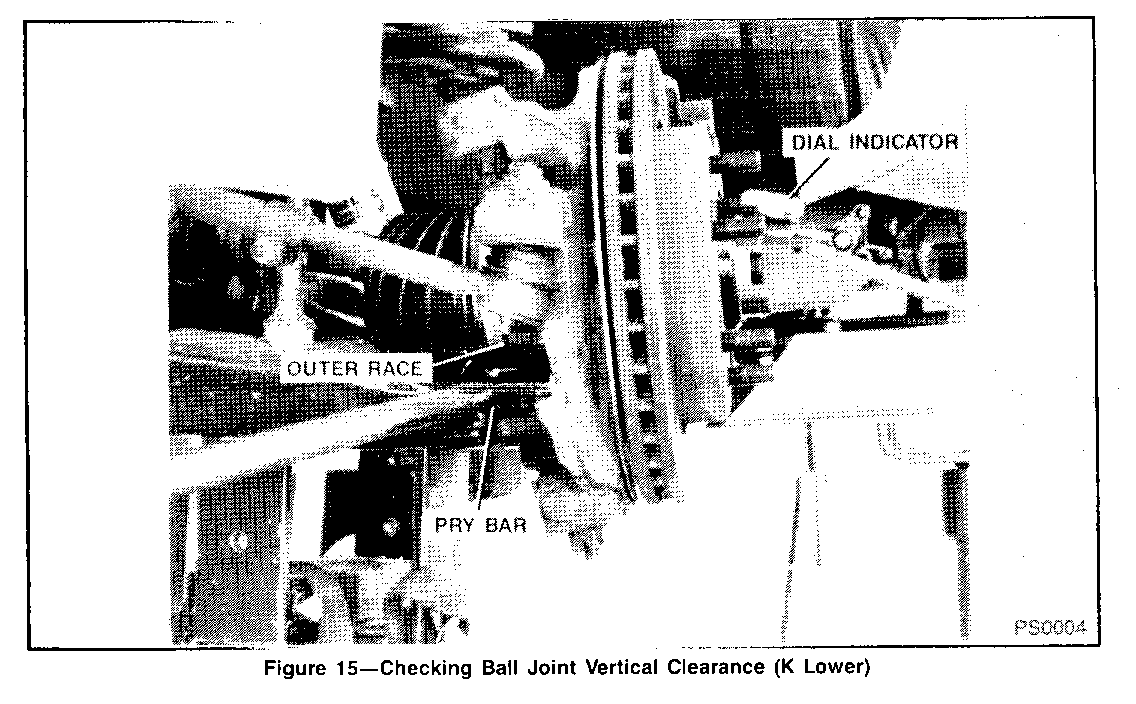
- With the vehicle on the jack stands, place dial indicator against the spindle to show vertical movement (figure 15).
- Pry between the lower control arm and the outer race while reading the dial indicator. This will show vertical looseness in the ball joints (figure 15).
- If the dial indicator reading is more than 1 nun (0.040 inch), replace the ball joint.
NOTICE: Do not pry between the lower arm and the drive axle seal or in such a manner that the ball joint seal is contacted. Damage to the seal will result (4WD).
1990 C and K MODEL UPPER
- Be sure the vehicle rests on a level surface.
- Raise and support front of vehicle with suitable safety stands. Support the lower control and with a floor stand or jack as far outboard as possible.
- The vehicle must be stable and should not rock on the floor stands.
- If the vehicle is equipped with aluminum wheels it may be necessary to first remove the wheel.
Check the Ball Joints for Vertical Looseness
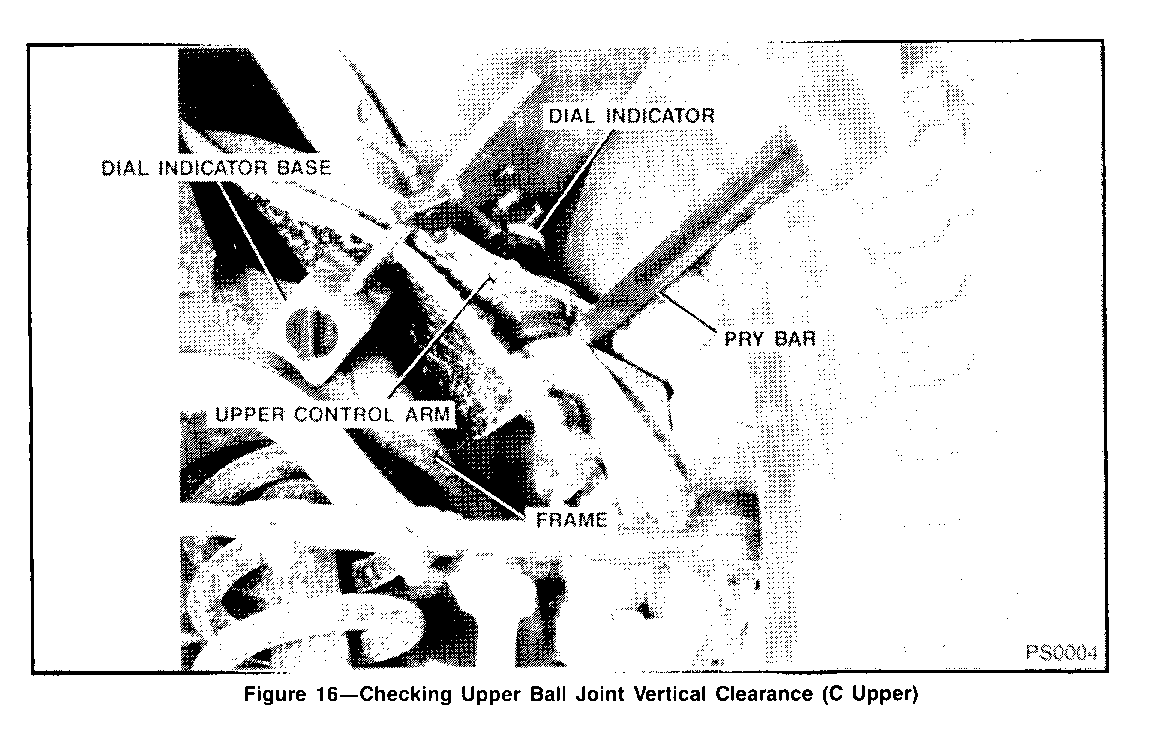
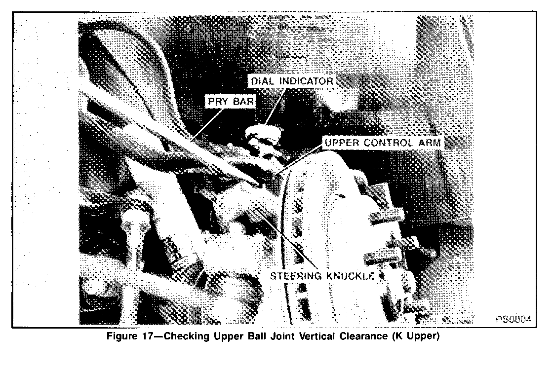
- With front of vehicle supported, position dial indicator with magnetic base on frame and measurement needle on top of the upper ball joint or control arm (figure - 16).
- With a pry bar pry between the upper control arm and steering knuckle while observing die dial indicator (figure 17).
- If the reading is more than 1 mm (0.040 inch) replace the ball joint.
NOTICE: Do not pry in such a manner that the ball joint seal is contacted. Damage to the seal will result.
SERVICE PROCEDURE:
MAINTENANCE-FREE BALL JOINT REPLACEMENT, UPPER & LOWER - 1988-89 C TRUCK
Required Tools:
J-23742 Ball Joint Separator J-9519-D Ball Joint Remover and Installer Set J-24319-01 Steering Linkage Puller
1. Raise vehicle and support it with safety jack stands.
2. Support lower control arm with a jack and secure spring with a safety chain.
NOTICE: Jack or stand must remain under the lower control and spring seat during removal and installation to retain the spring and control arm in position.
3. Remove wheel and tire assembly.
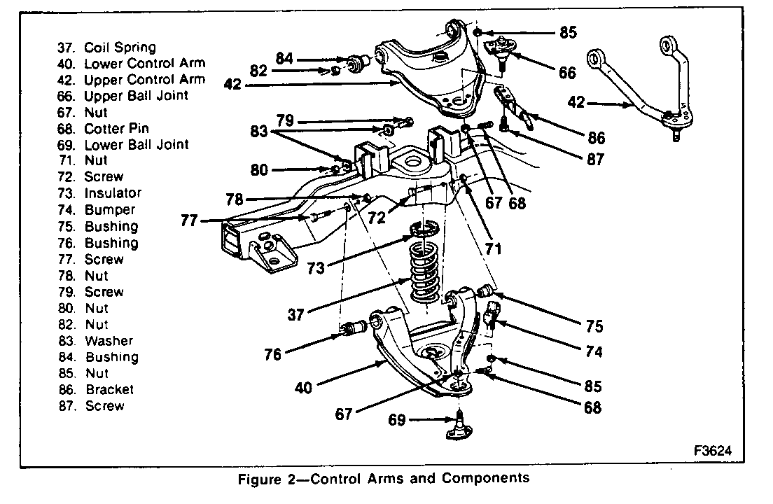
4. Remove brake line support (Figure 2, 86) from upper control arm (Figure 2, 42).
5. Remove brake caliper and rotor.
NOTICE Support caliper with a piece of wire to prevent damage to brake line.
6. Remove cotter pin (Figure 2, 68) and stud nut (Figure 2, 67) from upper ball joint (Figure 2, 66).
7. Remove upper ball joint (Figure 2, 66) from knuckle.
a. Support knuckle assembly.
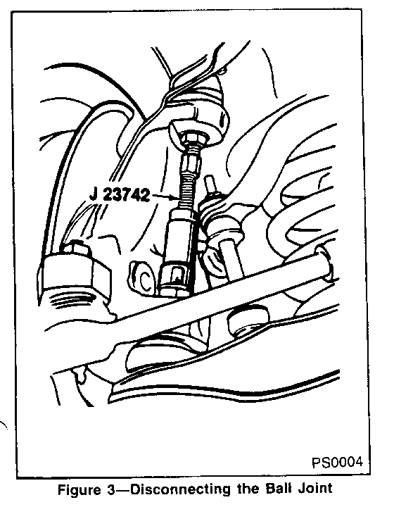
b. Use J-23742 as shown in Figure 3.
c. Inspect tapered hole in knuckle and remove any dirt. If hole is out of round, deformed or damaged, the knuckle must be replaced.
8. Remove rivets from upper ball joint (Figure 2, 66). If ball joint has been previously replaced, remove bolts and skip to step 9.
a. Centre punch top of rivets.
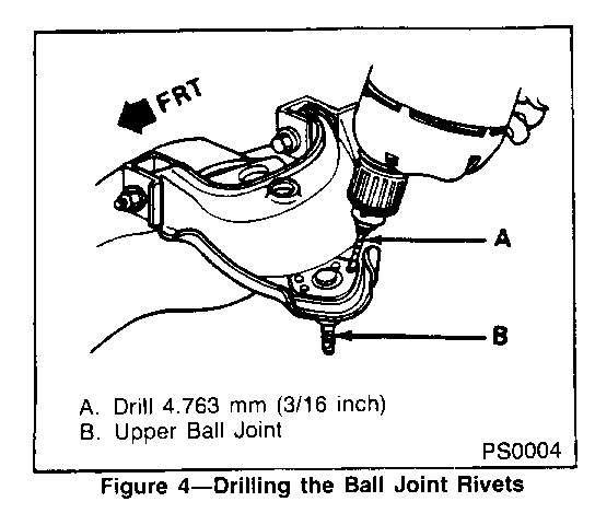
b. Use a 4.763mm (3/16-inch) drill to cut a 6.35mm (1/4-inch) deep hole in centre of each rivet (Figure 4).
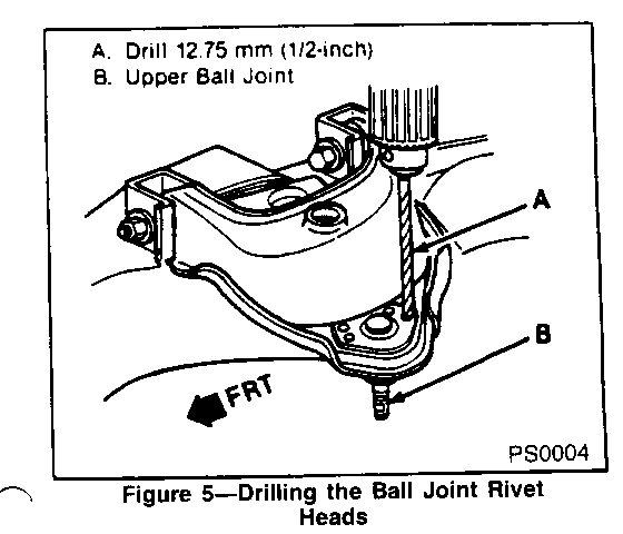
c. Drill rivet heads away using a 12.7 mm (1/2-inch) drill (Figure 5).
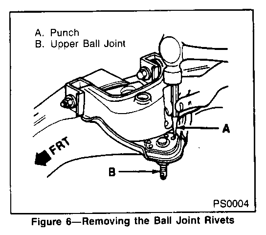
d. Punch rivets out using a punch (Figure 6).
9 . Remove upper ball joint (Figure 2, 66).
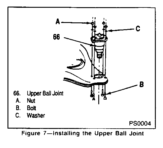
10. Install new upper ball joint (Figure 7, 66) to upper control arm (Figure 2, 42).
a. Position four attaching bolts (pointing upwards), washers and nuts.
b . Tighten nuts (Figure 7, A) to 23 N.m (17 lb. ft.)
11. Remove cotter pin (Figure 2, 68) and stud nut (Figure 2, 67) from the lower ball joint (Figure 2, 69).
12. Remove lower ball joint (Figure 2, 69) from knuckle.
a. Support knuckle assembly.
b. Use J-24319-01 to break ball joint loose from knuckle. or damaged, the knuckle must be replaced.
c. Inspect tapered hole in knuckle and remove any dirt. If hole is out of round, deformed
d. Move knuckle assembly aside and support.
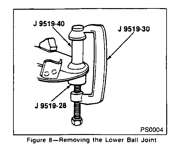
13. Remove lower ball joint (Figure 2, 69) from lower control arm (Figure 2, 40) using tools as shown in Figure 8.
14. Install new lower ball joint (Figure 2, 69) to lower control arm (Figure 2, 40).
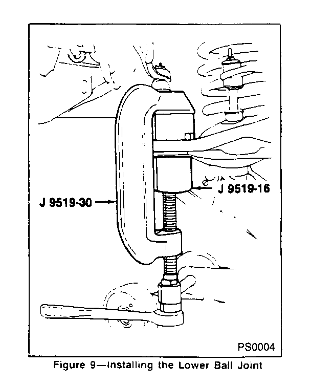
a. Press in ball joint using tools as shown in Figure 9. Ball joint will bottom on control arm.
15. Install new lower ball joint (Figure 2, 69) to knuckle.
16. Install lower stud nut (Figure 2, 67) and new cotter pin (Figure 2, 68).
a. Tighten stud nut (Figure 2, 67) to 128 N.m (94 lb. ft.).
b. Align slot in. stud nut with hole in stud by tightening stud nut.
c. Bend pin ends against stud nut.
17. Install new upper ball joint (figure 7, 66) to the knuckle.
18. Upper stud nut (figure 2, 67) and new cotter pin (figure 2, 68).
a. Tighten stud nut (figure 2, 67) to 100 N.m (75 lbs. ft.).
b. Align the slot in the stud nut with the hole in stud by tightening stud nut.
c. Bend the pin ends against stud nut.
19. Install brake rotor and caliper.
20. Install brake fine support (Figure 2, 86) to upper control arm (Figure 2, 42).
21. Install wheel and tire assembly.
22. Repeat procedure for opposite side of vehicle.
MAINTENANCE-FREE BALL JOINT REPLACEMENT, UPPER ONLY - 1990 C TRUCK
Required Tools: J-23742 Ball Joint Separator
1. Raise vehicle and support it with safety jack stands.
2. Support lower control arm with a jack and secure spring with a safety chain.
NOTICE: Jack or stand must remain under lower control arm spring seat during removal and installation to retain spring and control arm in position.
3. Remove wheel and tire assembly.
4. Remove brake line support (Figure 2, 86) from upper control arm (Figure 2, 42).
5. Remove brake caliper and rotor.
NOTICE: Support caliper with a piece of wire to prevent damage to brake line.
6. Remove cotter pin (Figure 2, 68) and stud nut (Figure 2, 67) from upper ball joint (Figure 2, 66).
7. Remove upper ball joint (Figure 2, 66) from knuckle.
a. Support knuckle assembly.
b. Use J-23742 as shown in Figure 3.
c. Inspect tapered hole in knuckle and remove any dirt. If hole is out of round, deformed or damaged, the knuckle must be replaced.
8. Remove rivets from upper ball joint (Figure 2, 66). If ball joint has been previously replaced, remove bolts and skip to step 9.
a. Centre punch tip of rivets. Use a 4.763mm (3/16-inch) drill to cut a 6.35mm (1/4-inch) deep hole in centre of each rivet (Figure 4).
b . Drill rivet heads away using a 12.7mm (1/2-inch) drill (Figure 5).
c. Punch rivets out using a punch (Figure 6).
9. Remove upper ball joint (Figure 2, 66).
10. Install new upper ball joint (Figure 7, 66) to upper control arm (Figure 2, 42).
a. Position four attaching bolts (pointing upwards), washers and nuts (Figure 7).
b. Tighten nuts (Figure 7, A) to 23 N.m (17 lb. ft.)
11. Install new upper ball joint (Figure 2, 66) to knuckle.
12. Install upper stud nut (Figure 2, 67) and new cotter pin (Figure 2, 68).
a. Tighten stud nut (Figure 2, 67) to 100 N.m (75 lb. ft.).
b. Align slot in stud nut with hole in stud by tightening stud nut.
c . Bend pin ends against stud nut.
13. Install brake rotor and caliper.
14. Install brake fine support (Figure 2, 86) to upper control arm (Figure 2, 42).
15. Install wheel and tire assembly.
16. Repeat above procedure for opposite side of vehicle.
MAINTENANCE-FREE BALL JOINT REPLACEMENT, UPPER & LOWER - 1988-1990 K TRUCK
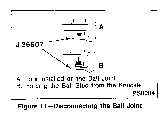
Required Tools: J-36607 Ball Joint Separator J-24319-01 Steering Linkage Puller
1. Raise vehicle and support it with safety jack stands.
2. Support lower control arm with jack.
NOTICE: Jack or stand must remain under lower control arm spring seat during removal and installation to retain torsion bar and control arm in position.
3. Remove wheel and tire assembly.
4. Remove brake caliper and rotor.
NOTICE: Support caliper with a piece of wire to prevent damage to brake line.
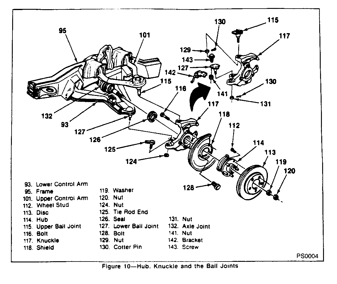
5. Remove cotter pin (Figure 10, 130) and stud nut (Figure 10, 129) from upper ball joint (Figure 10, 115).
6. Remove upper ball joint (Figure 10, 115) from knuckle (Figure 10, 117).
a. Support knuckle assembly.
b. Use J-36607 as shown in Figure 11.
c. Inspect tapered hole in knuckle and remove any dirt. If hole is out of round, deformed or damaged, knuckle must be replaced.
7. Remove rivets from upper ball joint (Figure 10, 115). If ball joint has been previously replaced, remove bolts and upper ball joint, and skip to step 9.
a. Centre punch top of rivets.
b. Use a 4.763mm (3/16-inch) drill to cut a 6.35mm (1/4-inch) deep hole in the centre of each rivet (Figure 4).
c. Drill rivet heads away using a 12.7mm (1/2-inch) drill (Figure 5).
8. Remove upper ball joint (Figure 10, 1 15) from upper control arm (Figure 10, 101). Rivets will remain in control arm.
NOTICE: Do not damage upper control arm mounting surface when removing ball joint or rivets.
a. Remove remaining rivet shanks flush with control arm.
b. Support upper control arm and punch rivets out using a punch (Figure 6).
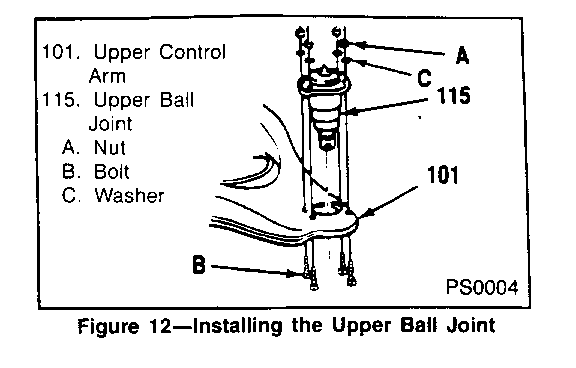
9. Install new upper ball joint (Figure 12, 115) to upper control arm (Figure 12, 101 - C Truck arm shown, K Truck arm typical).
a. Position four (4) attaching bolts (pointing upwards), washers and nuts.
b. Tighten nuts (Figure 12, A) to 23 N.m (17 lb. ft.)
10. Remove drive axle shaft nut (Figure 10, 120) and washer (Figure 10, 119) from hub assembly (Figure 10, 114).
11. Remove cotter pin (Figure 10, 130) and stud nut (Figure 10, 131) from lower ball joint (Figure 10, 127).
12. Remove lower ball joint (Figure 10, 127) from knuckle (Figure 10, 117).
a. Support knuckle assembly.
b . Use J-24319-01.
c. Remove drive axle from hub assembly at same time.
d. Move knuckle assembly aside and support.
e. Move drive axle aside and support.
f. Inspect tapered hole in steering knuckle and remove any dirt. If hole is out of round, deformed or damaged, knuckle must be replaced.
13. Remove rivets from lower ball joint (Figure 10, 127). If ball joint has been previously replaced, remove bolts and skip to step 14.
a. Centre punch top of rivets.
b. Use a 4.763nim (3/16-inch) drill to drill through centre of each rivet (Figure 4).
c. Use a 7.938mm (5/16-inch) drill to enlarge hole through the centre of each rivet.
d. Drill rivet heads away using a 12.7mm (1/2-inch) drill (Figure 5).
NOTICE: Use caution to avoid drilling through rivet head and into lower control arm.
e. Use a chisel and hammer to remove any remaining rivet head.
f. Punch rivets out using a small pin punch (Figure 6).
14. Remove lower ball joint (Figure 10, 127) from lower control arm (Figure 10, 93).
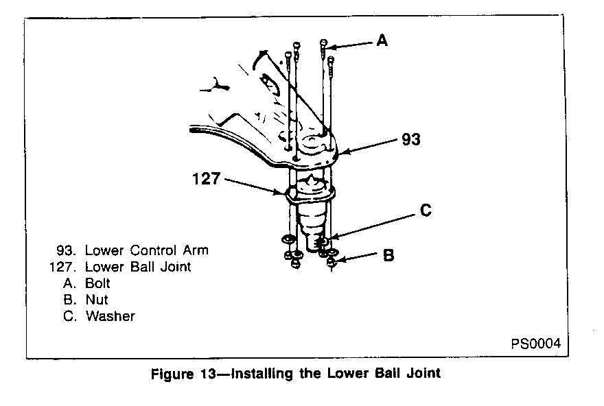
15. Install new lower ball joint (Figure 10, 127) to lower control arm (Figure 13, 93).
a. Ball joint is installed between flanges of lower control arm.
b. Position four (4) attaching bolts (pointing downward), washers and nuts.
c. Tighten nuts (Figure 13, A) to 60 N.m (45 lb. ft.).
16. Install new lower ball joint (Figure 10, 127) to knuckle (Figure 10, 117). Drive axle should be installed through hub assembly at same time.
17. Install lower stud nut (Figure 10, 131) and new cotter pin (Figure 10, 130).
a. Tighten stud nut to 128 N.m (94 lb. ft.).
b. Align slot in stud nut with hole in stud.
c. Bend cotter pin ends against nut.
18. Install upper ball joint (Figure 10, 115) to knuckle (Figure 10, 1 17).
19. Install upper stud nut (Figure 10, 129) and new cotter pin (Figure 10, 130).
a. Tighten stud nut (Figure 10, 129) to 100 N.m (75 lb. ft.).
b. Align slot in stud nut with hole in stud.
C. Bend cotter pin ends against nut.
20. Install washer (Figure 10, 119) and drive axle nut (Figure 10, 120). Tighten nut to 235 N.m (173 lb. ft.).
21. Install brake rotor and caliper.
22. Install wheel and tire assembly.
23. Repeat procedure on opposite side of vehicle.
PARTS INFORMATION:
Parts required to complete this Special Policy should be ordered through regular channels, as follows:
PART QUANTITY/ NUMBER YEAR MODEL DESCRIPTION VEHICLE ------ ---- ----- ----------- --------- 15657212 88-89 C 10-30 Lower Control Arm 2 Ball Joint Kit
15634942 88-90 K 10-30 Lower Control Arm 2 Ball Joint Kit
15659518 88-90 C/K 10-20 & C5Z Upper Control Arm 2 Ball Joint Kit
15634909 89-90 C/K 20 & C6P Upper Control Arm 2 Or C/K 30 Ball Joint Kit
15635534 1988 C/K 30 Upper Control Arm 2 Ball Joint Kit
15654867 88-90 C/K 10-30 Upper Control Arm 1 Alignment Kit
WARRANTY CLAIM INFORMATION:
When performing the repair as outlined in this bulletin, the Dealer is requested to submit a warranty claim for credit as follows:
WARRANTY INFORMATION
Dealers should submit a claim on each vehicle completed
LABOUR OPERATION TIME NUMBER DESCRIPTION ALLOWANCE --------- ----------- --------- T7306 1988-89 C-Truck, Replace 4 Ball Joints, 1.5 Hrs.
Delete:
- For EACH previously installed ball joint 0.1 Hrs.
T7307 1988-90 K-Truck, Replace 4 Ball Joints, 3.9 Hrs.
Delete:
- For EACH previously installed (bolted) ball joint 0.6 Hrs.
T7308 1990 C-Truck, Replace Both Upper Ball Joints, 1.1 Hrs.
Delete:
- For EACH previously installed (bolted) ball joint 0.1 Hrs.
T7311 Check and adjust toe-in alignment .3 Hrs.
T7309 Alignment Parts Kit Supplied to Customer 0.0 Hrs. Over the Counter - Use Kit Part Number
General Motors bulletins are intended for use by professional technicians, not a "do-it-yourselfer". They are written to inform those technicians of conditions that may occur on some vehicles, or to provide information that could assist in the proper service of a vehicle. Properly trained technicians have the equipment, tools, safety instructions and know-how to do a job properly and safely. If a condition is described, do not assume that the bulletin applies to your vehicle, or that your vehicle will have that condition. See a General Motors dealer servicing your brand of General Motors vehicle for information on whether your vehicle may benefit from the information.
